
Radio Control: Electrics
Bob Kopski
Playboy CG note
The PLAYBOY, again. Two months ago (January 1985 RC Electrics column) I described the 45%-of-chord CG (center of gravity) location on my Playboy. In some recent conversation with Roland Boucher of Leisure Electronics, I learned that the CG can actually be allowed to go back as far as 60%. While mine is going to stay where it is, those building Playboys still have some liberty with CG location. You'll recall that this unusually aft CG is permitted by the large, lifting stab of this popular OT (Old-Timer) design. Don't try this with contemporary designs — the results could be catastrophic!
Battery packs
Another reference to the January column seems worthwhile. At that time I described the assembly of a nine-cell, 0.8 Ah (ampere-hour) pack using silicone adhesive to glue the cells and some balsa separator strips together. I also noted that the method did not work out well: silicone simply did not have enough "stick" to the plastic cell coverings common to many packs.
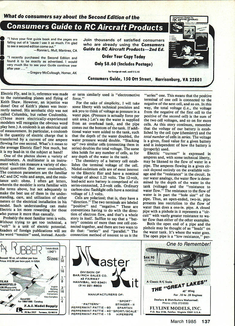
Packs assembled with cells glued together with CyA (cyanoacrylate) provide a very strong joint. However, if you ever need to remove a cell or reshape the pack, that strength makes disassembly difficult and often tears the plastic cell sleeves. The approach below permits a fairly strong pack assembly yet allows rework.
How to assemble a reworkable pack:
- Use ordinary 1/4-in. black vinyl auto-trim tape (pin-striping tape) wrapped near the cell ends. The tape is available in auto stores and in many colors.
- Wrap each cell end several layers; I used six wraps per cell end, but vary to suit your needs.
- Lay wrapped cells side by side with opposite polarities adjacent for easy wiring. Two wood strips pinned to the bench acting as rails help assure alignment.
- The tape-wrap "bumps" mate and slightly separate the cells.
- Apply a drop of CyA at the intersections of tape wraps (and a squirt of accelerator if desired) to bond tape to tape — take care not to let CyA dribble onto the plastic cell wrappers.
- Subpacks can be made (for example, a seven-cell pack of a three-cell and a four-cell subpack). Separate subpacks with strips of 1/8 x 1/4 in. balsa glued in place with CyA.
- If a cell must be removed, cut the top wrap layer of tape and substitute a suitably wrapped replacement without damaging the cells' plastic wrappers.
Benefits:
- Easier reworkability than gluing cells directly to each other.
- Built-in separations allow additional air circulation for battery cooling.
- Leftover trim tape can be reused for repairs and finishing.
Basic electrics — introduction
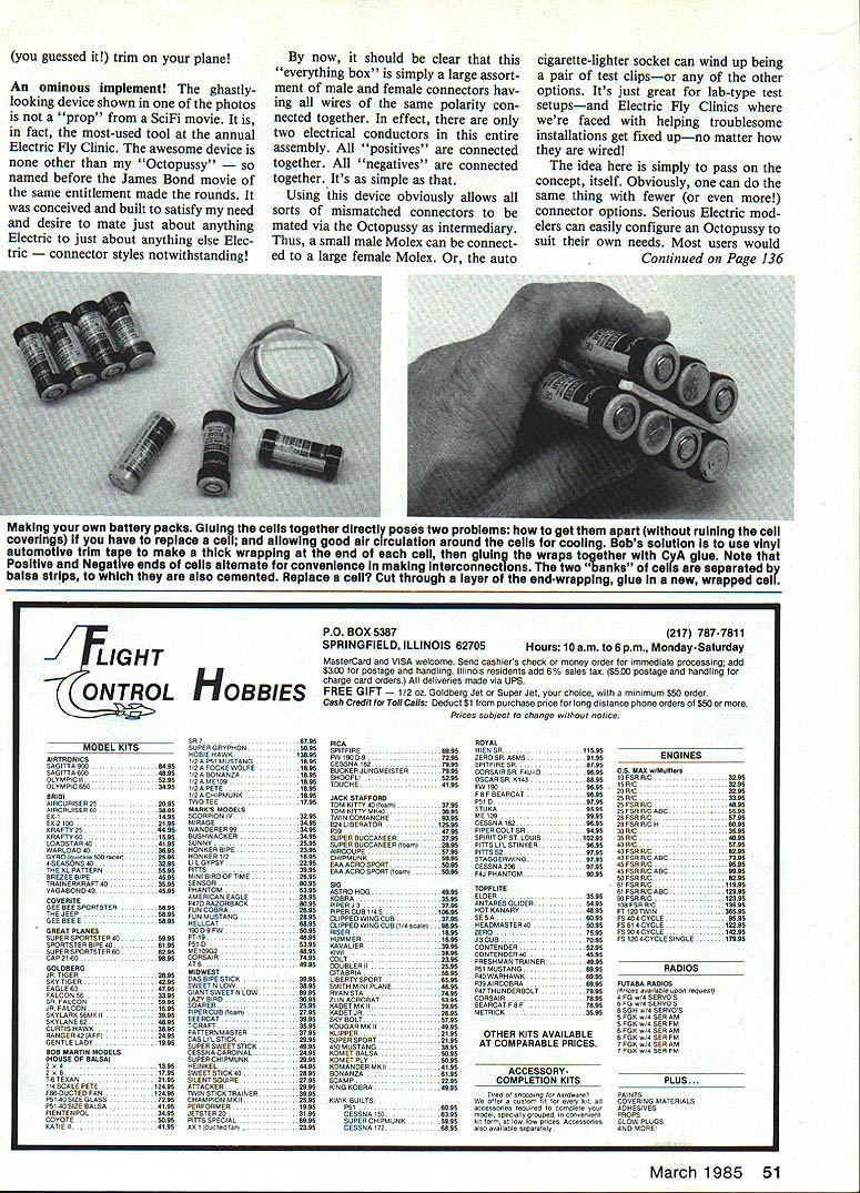
To get the most out of an RC electric installation you'll need to know some basic principles of electricity. I introduce the subject here and will continue in future columns, covering topics such as choosing and using simple metering (Simpson 261, Heath digital, Radio Shack analog/digital, etc.).
Coulomb and coulombia:
- A coulomb is the quantity of electric charge transferred by a current of one ampere flowing for one second.
- (A note about nomenclature: one of Keith Shaw's planes at the 1984 Electric Fly was incorrectly named in the January 1985 issue — it should have been "Coulombia," a play on "coulomb.")
Multimeters:
- A multimeter measures AC/DC volts, amps, and resistance (ohms). Understanding these terms makes electric flying more rewarding.
Volts:
- Think of voltage like water pressure in a tank. Increasing the number of cells in series "stacks" the voltage.
- Nickel-cadmium cells have a nominal voltage of about 1.25 V.
- A 12-volt lead-acid auto battery is six series-connected 2.0-volt cells.
- Carbon-zinc flashlight cells are about 1.5 V.
Series vs. parallel:
- Cells are polarized (positive and negative). In series, the positive of one cell connects to the negative of the next, summing voltages.
- The battery voltage is determined by cell chemistry and the number of cells in series and is independent of proper use.
Current and resistance:
- Electric current (amperes) is like the flow of water; it depends on available voltage and the resistance in the circuit.
- Ohm's law relates voltage (E), current (I), and resistance (R): E = I × R. Given any two, the third is calculated.
- Example: 12 V across 6 Ω gives 2 A. To limit current to 10 A on 12 V requires 1.2 Ω.
- Resistance depends on conductor length, cross-sectional area, and material resistivity. Use thick, short copper leads to minimize resistance.
- Power (watts) is P = E × I. Resistive losses are I²R and are dissipated as heat; minimizing lead and connection resistance reduces these losses.
R.B.'s "Octopussy" — connector interconnect box
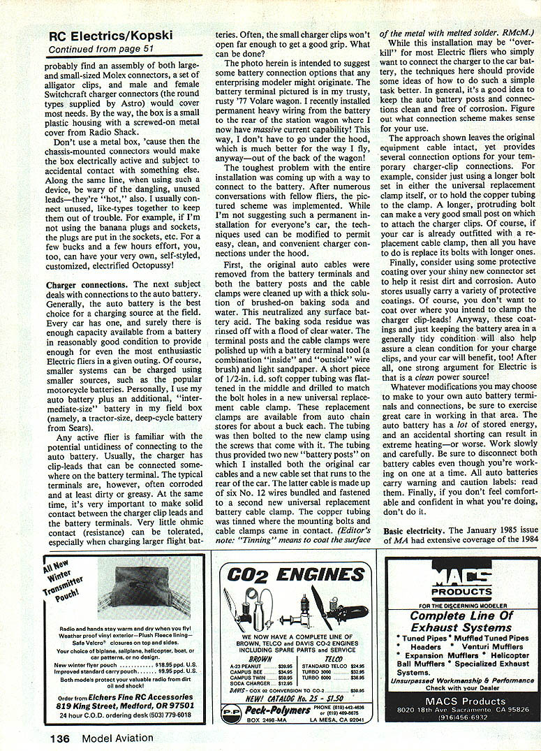
One of my favorite workshop devices is the "Octopussy" — a connector box conceived to mate almost any electric unit to any other regardless of connector style. The name predates the James Bond movie.
Concept:
- The box contains a large assortment of male and female connectors (Molex sizes, banana plugs, Switchcraft round charger connectors, cigarette-lighter plugs/sockets, alligator clips, etc.).
- All positive contacts are wired together; all negative contacts are wired together. Effectively, the box is just two conductors: a positive bus and a negative bus.
- This lets you connect mismatched connectors via the Octopussy as an intermediary: small Molex to large Molex, cigarette-lighter socket to test clips, etc.
Practical tips:
- Configure connector selections to suit your needs; most modelers will want large and small Molex, a set of alligator clips, and male/female round charger connectors.
- The box can be built in a small plastic housing with a screwed-on metal cover (Radio Shack sells suitable enclosures).
- Do not use a metal box unless the connectors and wiring are insulated from the chassis — chassis-mounted connectors would make the box electrically active and dangerous.
- Be careful of dangling unused leads — they are "hot." When not in use, plug like-types together (e.g., put plugs into sockets) or tie them off.
For a few dollars and a few hours you can build a customized Octopussy for lab-style testing, field clinics, and troubleshooting.
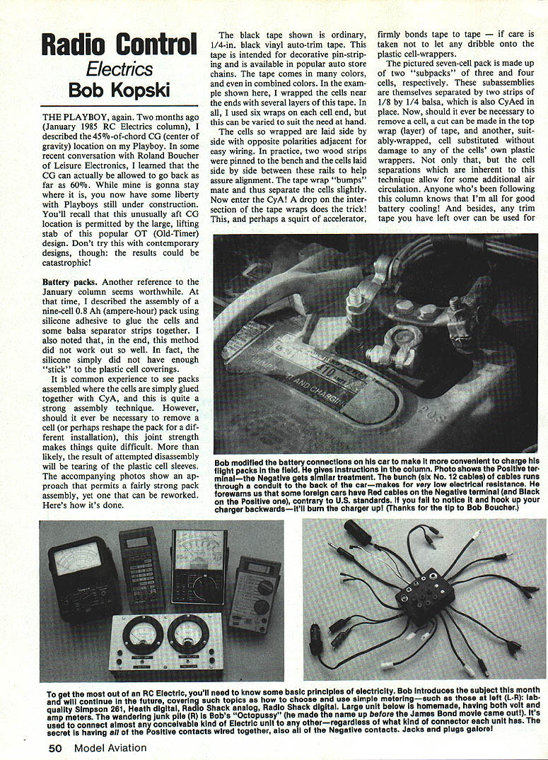
Charger connections (auto battery)
The auto battery is usually the best charging source at the field: every car has one and a reasonably good battery has enough capacity for even enthusiastic electric fliers. Smaller systems can use motorcycle batteries; I personally use my car battery plus an intermediate-size deep-cycle battery in my field box.
Common problems and solutions:
- Charger clip-leads often don't make good contact with dirty or corroded battery terminals. Poor contact introduces significant resistance that causes heating and poor charging.
- Small charger clips may not open far enough to get a good grip.
Field connection options and a durable installation (as implemented on my '77 Volare wagon):
- Remove the original auto cable clamps and clean posts and clamps with a thick brushed-on baking soda solution to neutralize acid. Rinse thoroughly with water.
- Polish terminal posts and clamps with a battery terminal tool (inside/outside brush) and light sandpaper.
- Use a short piece of 1/2-in. i.d. soft copper tubing flattened and drilled to match the bolt holes in a universal replacement cable clamp. Bolt the tubing to the clamp with the clamp's screws.
- The tubing provides one or more new "battery posts" where you mount both the original car cables and a new cable set running to the rear of the car.
- My rear-run cable is six No. 12 wires bundled to provide very low resistance back to the cargo area, simplifying field charging from the back of the wagon.
- Tin the copper tubing where mounting bolts and clamps contact it. (Editor's note: "tinning" means coating the metal surface with melted solder.)
Alternate, simpler options:
- Use a longer bolt in the replacement clamp or to hold the copper tubing, forming a protruding post for charger clips.
- If your car already has a replacement cable clamp, simply replace its bolts with longer ones for clip attachment.
Protective measures:
- Use protective coatings from auto stores on shiny new connectors to resist dirt and corrosion — avoid coating the clamp surfaces where charger clips must make contact.
- Keep terminals and connections clean to maintain low contact resistance.
Safety and cautions:
- Be mindful that some foreign cars have reversed color coding (red to negative and black to positive). Verify polarity before connecting; reverse connection can destroy chargers.
- Exercise great care when working on batteries: disconnect both battery cables before working, read all battery warning labels, and do not proceed if you are uncomfortable or unsure.
- An accidental short can cause extreme heating or worse.
Practical notes and closing
- Good battery cooling and low-resistance wiring are two keys to reliable electric flight.
- A simple multimeter and a basic understanding of volts, amps, resistance, and power will make you a much better electric modeler.
- Build simple tools (Octopussy, durable battery hookup) to make field work easier and safer.
- Work carefully and keep connections clean and well maintained — your equipment (and your car) will thank you.
Transcribed from original scans by AI. Minor OCR errors may remain.

