
Radio Control: Electrics
Bob Kopski 25 West End Dr. Lansdale, PA 19446
This Month's Topics
- Some personal notes
- Electric Connection Service
- More on motor/speed-control glitching
- Reader preference: a question unanswered
- Vintage RC (Electric and otherwise)
- Electric installations
Personal Notes
Last month's column opened with some personal notes which included, among other things, an explanation of why I've not been responsive to your letters for a few months. I strive to get back to normal in this regard—wherein "normal" means I respond to reader mail promptly—but as I write this (late October), I still have an enormous pile of mail on my desk dating back to late summer, with more accumulating nearly every day.
To put things in perspective, reader mail in any given month normally demands significantly more time and work than writing a column. My personal situation still does not allow me to readily accommodate that mail, so I must continue to ask your indulgence in this regard. Again, when things are normal, I'll let you know. If you're wondering what this is all about, please review the January 1991 issue.
Electric Connection Service
The Electric Connection Service is now 13 months old, having been introduced in the January 1990 issue. Over the year many readers have requested to be listed in this column. This service attempts to connect local electric modelers who are unaware of each other—i.e., those who feel "they are the only ones flying electric." Because this service has proven successful for many, it will continue as a column feature as long as readers continue to ask for this assistance. Just let me know in writing, and presto, your name will appear right here in Model Aviation! Remember, it takes about three months for this to happen.
This month features the following folks who'd like to hear from other electric fliers in their area:
- Bill Bates, 20 Hemlock Drive, Glen Mills, PA 19342; 1-215/459-4882. Member Salem County R/C Club, New Jersey; SAM 66, Wilmington, Delaware. Modeler with long-time experience.
- Chris Stratton, P.O. Box 52, Canton Center, CT 06020. Has special interest in home-brew speed controls. (He also acknowledges still flying some fuel-to-noise conversions. That's okay, Chris; there's still enough time to right the wrongs of the world, including this one!)
- Bob Ortman, 631 Sobrato Way, Campbell, CA 95008. Aside from finding locals to convert to electric persuasion, Bob would like to hear from folks interested in electric ducted fans and Keller motors.
- William Dashiell, 9405 Gwynndale Drive, Clinton, MD 20735. New to RC electrics; would like to hear from local fliers.
Motor / Speed-Control Glitching
Glitching caused by motor noise is a topic this column has addressed many times over the years, offering suggestions to try for a particular installation. One thing I have learned is there is no single solution to glitching problems because installation and equipment variables differ. Thus I'd normally expect several potential solutions; you may have tried to find ones that work.
I've recently heard a new glitching story and, continuing in the spirit of providing electric help, I'd like to pass along a problem a fellow club member has been having for a long time. Basically, suggestions to date have not been fully successful, including chokes I've mentioned several times, which have proven great success for many readers (see MA December 1989). Symptoms of the situation were mostly the motor changing speed and control-surface movement in the air; it looked and sounded just like other glitching situations. In this case, however, it turned out the receiver supply voltage that also powered the speed control fluctuated when a servo was moved, and the voltage variation, in turn, affected the speed-control operation. This was not a case of radio static—only the speed control was affected.
There are several things that can come into play here:
- Speed-control sensitivity. Some speed controls are sensitive to variations in receiver-system voltage; others are much less so.
- Battery, switch, wiring, or connectors. These items may have enough resistance or an intermittent contact to drop the voltage at the receiver when a servo draws current. Make sure you have a good, heavy-duty battery and solid connectors. Soldered joints or gold-plated connectors are best; cheap tin-plated connectors can develop high resistance.
- Wiring layout and routing. The motor, motor leads, and speed control may be close enough to the receiver or antenna to inject interference. Keep the motor and its leads well away from the receiver and antenna. If leads must cross, do so at right angles.
- Bypass capacitors across the receiver power leads can help absorb transient current surges and reduce voltage dips. Values used successfully include a 470 to 1,000 µF electrolytic with a 0.1 µF ceramic in parallel, mounted close to the receiver power pins.
Other approaches are using a separate battery for receiver and servos, or using a speed control that provides a regulated output for the receiver. Also try receiver-mounted ferrite chokes on servo leads.
In the fellow’s case, fitting a larger battery, repairing suspect connectors and adding a small electrolytic at the receiver power pins reduced the problem considerably—in fact, the glitching stopped altogether.
There must be actual variation of the receiver-system voltage, most likely to occur when a servo is moved because that's when the largest current demand takes place. Such variation could take place right at the battery terminals for batteries that are not in the best of condition (i.e., batteries with relatively high internal resistance). This could be the case with receiver packs that have seen years of service or for those that may have had some abuse.
However, it is also possible to have receiver-voltage variation—battery condition notwithstanding—if something in the receiver wiring is resistive. The most likely suspects would be connectors, or possibly the switch. Thus, for receiver-circuit resistance in the battery and/or wiring, current demand from a moving servo could cause enough voltage variation to affect the operation of speed controls prone to act this way in the first place. In turn, the motor could react with a speed change giving the clear impression of a radio-static glitching problem when it isn't really one.
Modern Electric-System Installation
Modern electric-system installation (what else right after a vintage discussion?) was a topic in the January issue, the October column and was planned as a short, continuing series. This is the second installment. It wasn't expected to be so distant in time from the first.
The idea behind this mini-series is to help you get past the store-bought or packaged systems and set about doing your own electric wiring with confidence. The idea for this topic came from talks given at a local club meeting where lots of interested folks were eager to learn how to do it themselves.
But why custom instead of just store-bought? There are many reasons. Personally, I've never found a ready-made system that fully satisfied my needs and interests. For example, I like to use a wide variety of products and this often makes for incompatible connectors. To deal with this, I have chosen to use a limited number of connector styles, and all my planes are so equipped.
I always fuse my systems. Some manufacturers don't, or do so improperly. I insist on not plugging into my planes and undoing some system connectors to charge. I always have a charge connector right on the fuselage so the model is completely ready to accept the charger connection. In addition, rare as it is that a packaged wiring harness fits right into a plane, it seems there is never enough wire length, or there is much too much—with too many bulky connectors—so that squeezing it all in can be a real challenge at times.
This mini-series will illustrate and discuss custom-installation wiring techniques that work well for me. Of course, your personal preferences can dictate the particular details of your custom wiring installation. The idea here is only to show examples—and how easy it is to do it yourself.
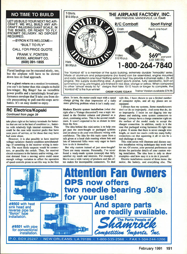
Electric installations consist of three items: the motor, the battery, and everything else. The motor and battery usually get the greatest attention. The "everything else" is usually the speed control, connectors, wiring, switches, fuses, perhaps a receiver pack, and so on.
Battery Packs and Custom Interconnection
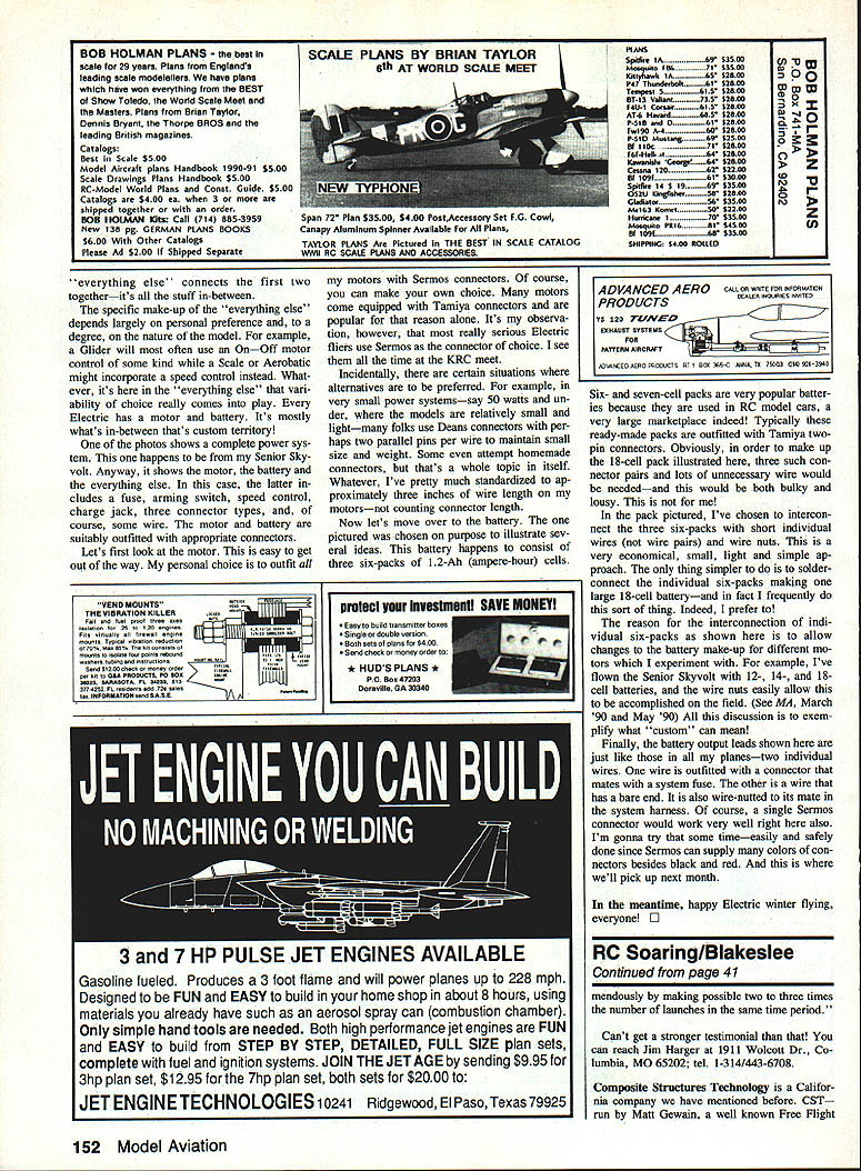
Six- and seven-cell packs are very popular batteries because they are used in RC model cars—a very large marketplace indeed! Typically these ready-made packs are outfitted with Tamiya-type connectors and lots of unnecessary wire and connectors. Obviously, in order to make up the 18-cell pack illustrated here, three such connector pairs and lots of unnecessary wire would be needed—and this would be both bulky and lousy.
In the pack pictured, I’ve chosen to interconnect the three six-packs with short individual wires (not wire pairs) and wire nuts. This is an economical, small, light and simple approach. The only thing simpler to do is to solder-connect the individual six-packs making one large 18-cell battery—and in fact I frequently do this sort of thing. Indeed, I prefer to!
The reason for the interconnection of individual six-packs as shown here is to allow changes to the battery make-up for different motors which I experiment with. For example, I’ve flown the Senior Skybolt with 12-, 14-, and 18-cell batteries, and the wire nuts easily allow this to be accomplished in the field (see MA March 1990 and May 1990). All this discussion is to emphasize how “custom” can mean.
Finally, the battery output leads shown here are just like those in all my planes—two individual wires. One wire is outfitted with a connector that mates with a system fuse. The other is a wire that has a bare end and is wire-nutted to its mate in the system harness. Of course, a single multi-pin connector would work very well here also. I’m going to try that sometime—easy and safe since many manufacturers offer connectors in colors besides black and red. And this is where we’ll pick up next month.
Closing
In the meantime, happy electric winter flying, everyone!
Transcribed from original scans by AI. Minor OCR errors may remain.

