
Radio Control: Electrics
Bob Kopski 25 West End Dr. Lansdale, PA 19446
Abstract
This month's topics:
- Electric Connection Service
- Reader reaction to the January 1991 column
- Notes from industry
- Electric installations, Part Three
Electric Connection Service
Word of an electric club forming in the Fairfield County area of Connecticut comes from Al Yeagle (84 Goldenrod Ave., Bridgeport, CT 06606). I’ve met Al at several Pennsylvania meets during the last two years. Call Al at 1-203-371-5613 for more information about what's happening electrically in his area.
Alternatively, write to Ed Bassick at 70 Limerick Rd., Fairfield, CT 06430, or call 1-203-259-2855.
Best wishes to this new club — tell ’em Bob sent you!
Reader reaction to the January 1991 column
The January 1991 Model Aviation column prompted several thoughtful responses. I received letters — including one from a CL flier with no electric interest who nonetheless reads all MA columns — and one from a first-time reader. A few people also telephoned with sympathy. I’m moved by the kindness shown and wish to thank everyone for their support during this trying time. Our hobby’s community is truly amazing.
Industry items of note
Astro
- Bob Boucher of Astro reports that the arming switch and charger jack mounted in the side of an Electric Seniorita use the mating plug from the charger. The jack and plug are Astro part numbers 4030 and 4029; each is $2.50 — a preferred way to charge.
- Astro has developed a new cobalt motor called the Whisper, intended as a replacement/upgrade for the motor supplied with the Kalt Whisper electric RC helicopter kit. Based on the Astro 035 cobalt, it uses tailored magnets, housing steel, and a special winding tuned for that installation. As with other Astro cobalts, it has replaceable brushes.
- Astro also developed a new brush variation that dramatically reduces brush heat and extends brush life by a factor of seven to eight, while greatly reducing commutator wear. This improvement will be incorporated in Astro motors and may reduce radio brush noise as a side benefit.
Other industry notes
- CS Flight Systems is expanding its product line and now carries Leisure products, including many electric items from Roland Boucher. Contact: CS Flight Systems, 31 Perry St., Middleboro, MA 02346.
- Idealair Models (Phil Alvarez) offers supplies for smaller electrics, including an extremely light iron-on covering material called Litespan (several colors, dull or shiny sides). Contact: Box 4485, Detroit, MI 48244-0485 (phone 1-519-974-8790). In Canada: Box 101, Old Castle, Ontario N0R 1L0.
Meet reports and examples
- Bill Passarelli (Williston Park, NY) won a fully equipped Astro Porterfield at the 1990 KRC Electric Fly; four were built and test-flown, and KRC members gave them away in that year’s raffle.
- David Eltringham (West Chester, PA) gave a convincing Electric Whisper display at the 1990 KRC meet. His Kalt Whisper uses a Mabuchi 540BS motor on a 9.6V 1100 mAh pack and includes microgyro, servos, speed control, collective cyclic pitch (optional), and autorotation capability.
Electric installations — Part Three
(This continues the series begun in the October 1990 and February 1991 Electric columns. Parts One and Two covered general installation topics; this month covers more specific how-to details and wiring specifics.)
Last month’s photo showed the three items common to all electric installations: the motor, the battery, and the “everything else” that fits between them. Refer to that photo while reading the wiring specifics below. The wiring shown is typical of my electrics; I use variations sometimes, but the basics remain the same.
Fuse location
- Always install a fuse immediately after the battery. I make this a personal standard. Fusing the positive lead is common; fusing the negative lead works equally well. The main point is to use a fuse located right after the battery to assure the greatest protection possible.
- Some factory harnesses put the fuse at the motor; that protects the motor but leaves most of the system wiring unprotected. Better than no fuse, but not ideal.
- A simple guideline: place as much of your system after the fuse as possible. This is analogous to residential service where the main fuse protects the house wiring at the service entrance.
Arming switch
- The arming switch is second in importance only to the fuse. I install the arming switch right after the fuse, electrically in the positive power line, though it can be placed in the negative line as well.
- The arming switch does not directly turn on the motor. Instead it "arms" the system so the motor can be turned on by some other means (servo-driven on/off switch, radio-controlled electronic switch, or an electronic speed control). When the arming switch is off, the motor cannot be turned on — preventing accidental start-up.
- Arming-switch rules:
- The arming switch is the last thing turned on before launch.
- The arming switch is the first thing turned off after landing.
- Place the arming switch where it’s easy and safe to reach (for example, on the model at a spot where a spinning prop can’t bite).
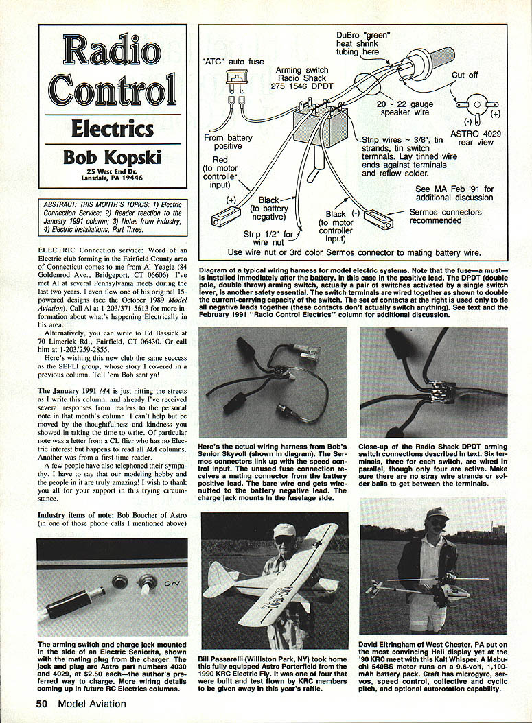
Recommended switch and wiring technique
- I typically use Radio Shack catalog #275-1546, a miniature DPDT toggle switch. DPDT = double pole, double throw:
- Double pole: two separate switches activated by the same lever.
- Double throw: each switch has two positions (two fixed contacts) for the moving contact.
- Each independent switch has three terminals (moving contact + two fixed contacts), so the DPDT has six terminals total.
- I wire the three sets of corresponding terminals of both switch halves in parallel to effectively double the current-carrying capacity. This is efficient, low-cost, and low-weight.
- In the wiring scheme described here:
- The battery positive goes to the fuse input.
- The fuse output becomes the arming switch input.
- The arming switch output relays positive power to the next component (typically a speed control).
- The inactive tie points on the switch are used as convenient connection points for negative system wires: battery negative, negative power input to the speed control, and the system charge jack.
- Only four switch terminals are actually required to arm/disarm the system; the other two are used as tie points for wiring convenience.
- Note: Different switches may have different terminal orientations or lever directions. Verify which contacts are which before wiring. In some switches, the closed contacts lie opposite the lever direction. Decide which lever position you want for "on" (up, forward, back) and confirm the switch’s orientation. I generally wire my switches so that throwing the lever back (opposite the direction of flight) turns the system on; in a crash this tends to throw the lever forward to off.
Wiring and soldering details
- Use appropriate wire: Du-Bro green 20–22 gauge speaker wire is mentioned as suitable for some control wiring; motor and battery leads will usually be heavier gauge as required by current draw.
- Strip wires and tin the positive strands and the switch terminals. Lay tinned motor or battery wire ends against terminals and reflow solder to make secure joints.
- Controller negative = black. Motor positive = red (follow your system color coding).
- Strip about 1/2" of input wire at the battery case and use a wire nut or a third-color servo connector to mate battery wires as needed. Wire nuts are convenient for battery case connections; a mateable connector can simplify battery removal.
- Use an ATC auto fuse or another appropriate fuse type sized for your system. The fuse must be installed immediately after the battery case positive lead (or negative if you choose).
- Make sure all switch and battery wiring is neat, with no loose wire strands or solder blobs that could short. Soldering all six switch terminals can be a multi-hand job — use clamps or holding devices to hold components during soldering.
Summary wiring scheme
- Battery positive -> fuse -> arming switch input -> arming switch output -> speed control (or other motor controller) positive.
- Battery negative -> switch tie point / system negative bus -> speed control negative and charge jack negative as required.
- Charge jack and other components should be placed after the fuse and arming switch as appropriate for safe charging and operation.
Next month’s continuation will include more system wiring discussion and how-to detail. In the meantime, happy, quiet, and safe landings, everyone!
Radio Control: Electrics Bob Kopski 25 West End Dr. Lansdale, PA 19446
Transcribed from original scans by AI. Minor OCR errors may remain.

