
Radio Control: Electrics
Bob Kopski 25 West End Dr. Lansdale, PA 19446
Note: See correction page 20.
THIS MONTH'S TOPICS:
- Electric Connection Service
- Some missing text from the February column (Electric events, Vintage RC)
- Electric installations, Part Four
- Personal closing thoughts
The Electric Connection Service
The Electric Connection Service has one offering this month:
- Dick Hinekle, 6406 E. 140th Terr., Grandview, MO 64030. Dick is eager to find others in his area who share in the joy electrics brings. If you know someone out there, let Dick know and tell him "Bob sent ya."
(Somehow, some text intended for the February issue did not appear in the final version of the column. Since I suspect readers were, at least somewhat, confused by the omission, I'm including the lost words in the sections that follow. Last‑minute space considerations when the magazine went to press forced us to delete the portion of the February "RC Electrics" column that Bob mentions. Model Aviation regrets the inconvenience.—Ed.)
Electric events
The October 1990 Electrics column requested that you write and tell me which types of events you prefer at electric meets. Specifically: what's your choice—formal AMA contest events or fun‑fly ones? Judging by reader response, I'd have to suppose that no one is interested in anything. I always knew electric fliers were low‑key, fun‑loving people, but I never expected to hear nothing at all.
I could go to one extreme and conclude that electric modelers simply aren't interested in meets. But that would be at odds with the steady growth in both the number of meets and the number of modelers attending them. Alternatively, it could mean that folks like meets but just don't get charged up over events—of any kind. In fact, at the 1990 KRC meet some prizes went unclaimed because there was no interest (see the January 1991 Electrics column). Perhaps meets structured as fly‑ins with no events and no prizes would be just as acceptable to most of you.
I do know for sure that electric fliers like to gather—and show‑and‑tell and peck and poke at each other's planes on the flight line. Maybe that's all that's needed. After all, the hobby is for fun, and fun can happen without any competitive goals. It's a matter of personal preference—and majority interest. Now, may I please have some reader response on this matter?
Vintage RC
In the October 1990 column I described my newly constructed electrified Trixter Beam with rudder‑only escapement control that I was readying for the Labor Day weekend Vintage bash at Selinsgrove, Pennsylvania. That meet could very well have been the high point of my summer, but I never made it due to the circumstances described in the January 1991 column. In good time, however, folks had a chance to see how well the Beam flies. The vintage plane had turns in the air at the Lehigh Valley (Pennsylvania), Burlington (Bergen County, New Jersey) and KRC meets.
The October column caught the attention of several readers. Some requested information about a custom circuit I mentioned that uses modern radios to drive escapements. I do not have readily reproducible prints for the circuit, but if reader interest continues I'll develop them so you can give it a try. Incidentally, the circuit, which connects a contemporary radio receiver to a vintage escapement actuator, isn't limited to electrics—it's useful even if you fly glow power. I've had a great deal of enjoyable flying my escapement electric this past summer, and I'm sure many of you would welcome the same opportunity.
Prior to the Vintage meet, I had also been working on an Esquire intended to fly with a Mighty Midget Galloping Ghost installation. This was also to be operated with a contemporary radio system. Though I haven't completed the project, I hope to retrieve it someday. If it's successful I'll pass that info along as well.
Now, in case some of you wonder why anyone would like flying such old junk—it's for the same reason one flies anything: fun. It's all a matter of individual perspective.
Modern Electric system installations (Part Four)
This ongoing mini‑series showing the different ways (and whys) I make custom installations in my electrics continues with Part Four this month. The idea is to help you "roll your own" with confidence. You might want to dig out the last few issues to have the earlier chapters handy as you read.
Last month's installment discussed and illustrated a typical wiring harness for model electric systems, with particular attention to the battery switch. Remember, an electric installation consists of a motor, a battery and an "everything else"—the stuff you need to connect them. This month we'll take a look at another component in the everything else—the optional charge jack.
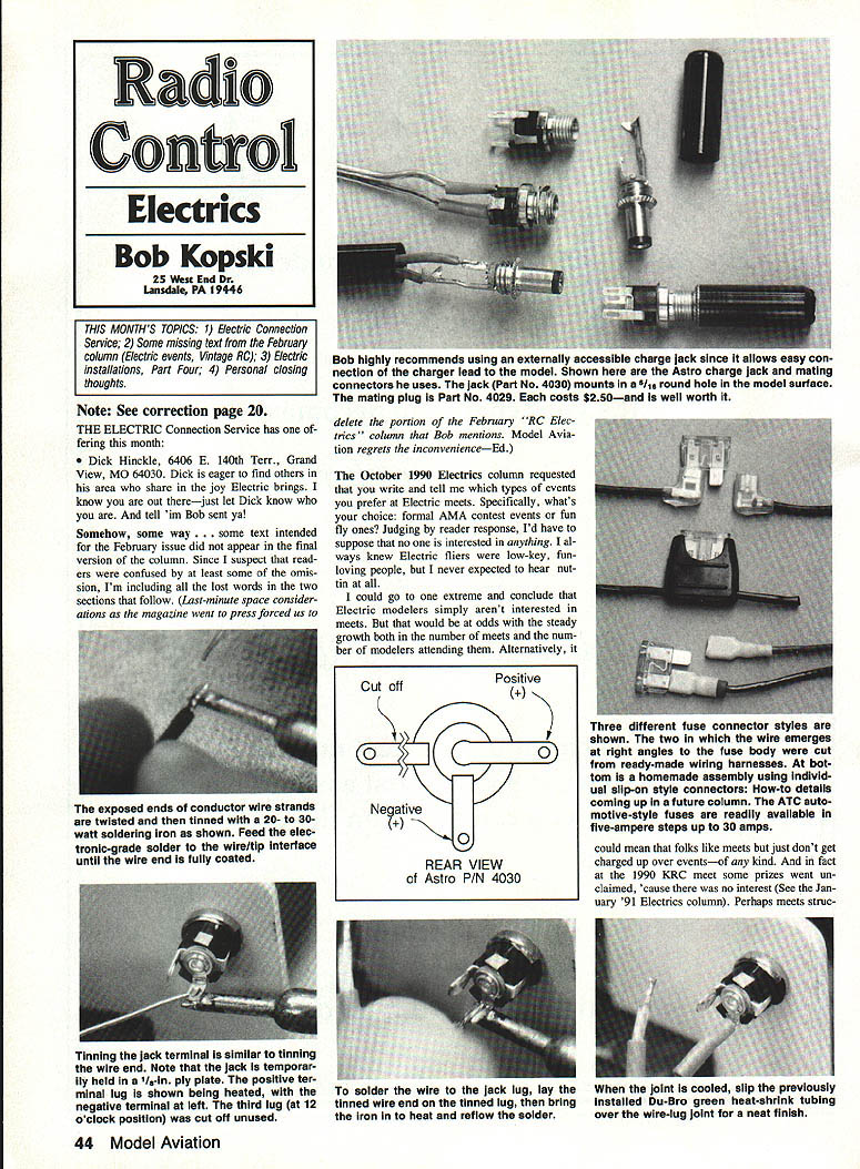
I'm absolutely, positively sold on using an externally accessible charge jack on my planes, as shown in one of the photos last month. Such a jack is one of the two ways most fliers connect a charger. It allows easy connection of the charger lead to your model: just plug in to charge and pull out when you're finished. The alternative is to get into the battery area of the model, disconnect the battery connector, connect to a mating one on your charger, disconnect when finished, reconnect the model wiring, and close up whatever access you opened to get at the connector. Whew!
Sometimes it seems that more people use the latter method than use the former. Why? Many store‑bought systems are sold without a separate charge jack. Another reason is that many folks like to remove batteries between flights (to cool them down or change to new ones), so they have to undo the model wiring connectors anyway.
If and when cooling is necessary, I prefer to do the job with a small external blower. Also, unless I'm experimenting, I never remove a battery to substitute another. Finally, I simply don't like messing with a tidy installation and putting wear and tear on the connectors. That's why all my electrics have charge jacks mounted on the model fuselage. Please note this is a matter of personal preference; there is absolutely nothing wrong with the other approach.
One photo shows the charge jack and mating connectors with their wiring connections. Astro supplied these parts with its flight systems and chargers since the early 1970s, but it recently stopped doing so. I have used several types of jacks; my personal favorites are the switchcraft‑type small "PJ" jacks which cost about $2.50 and are well worth it.
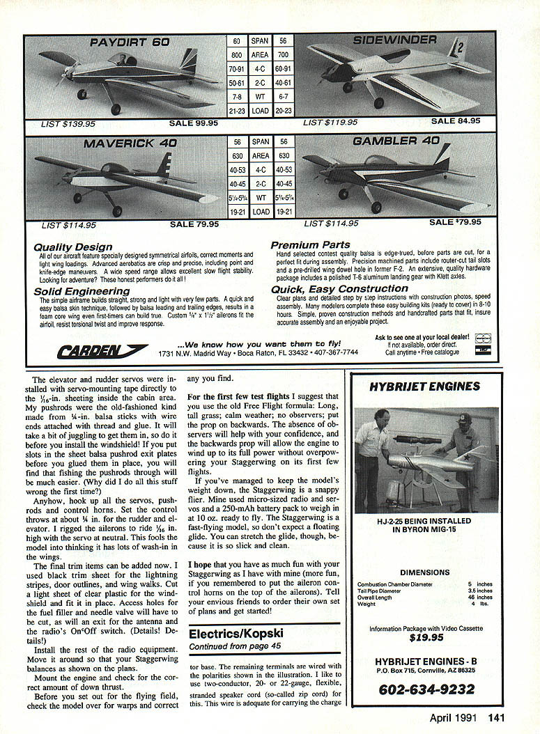
Astro PIN 4030: solder wire to jack lug. The jack mounts in a 5/16‑in. round hole in the model surface. The remaining terminals are wired with the polarities shown in the illustration. I like to use two‑conductor 20‑ or 22‑gauge flexible stranded speaker cord (so‑called zip cord) for this. This wire is adequate for carrying the charge current and is easy to work with.
Tinning and soldering technique (general guidance):
- Carefully separate the two insulated conductors by slicing the intermediate web for about 1/4 in. Strip about 1/8 in. of insulation off each wire end, taking care not to cut any strands. If you cut strands, start over.
- Twist the exposed strands tightly and tin (solder) the ends using a 20–30 watt soldering iron and electronic‑grade solder. Feed solder to the wire/tip interface until the wire end is fully coated.
- Tin the jack terminal in a similar fashion. It helps to hold the jack in a temporary scrap 1/8‑in. plywood plate clamped in a vice while you solder.
- Lay a tinned wire end against the tinned plated solder terminal and reflow the solder with the iron. Make a neat, smooth, compact joint. The wire can rest on either the inside or outside of the terminal.
- Slip 1/8 in. Du‑Bro green heat‑shrink tubing over each wire before final soldering; after soldering, slide it over the junction. Generally it fits snugly and needn't be heat‑shrunk, but a hot‑air gun works well if you do shrink it.
- Inspect soldered areas carefully for stray strands or solder balls that could short. Clean and rework as necessary.
Outfitting the charger output cord with the mating plug:
- Cut off whatever connector(s) are presently on the cord. Charger output cords are often conventional 18‑gauge zip or lamp cord, though some have individually insulated wires.
- Separate the two conductors about 1/2 in., and cut the negative wire 3/8 in. shorter than the positive one (you must determine polarity first).
- Strip both wires 1/8 in. and tin them.
- Unscrew the plastic barrel from the metal plug assembly and slip the barrel over the charger cord, threaded end last.
- Tin the two solder terminals of the plug. The negative (shorter) wire connects to the longer of the two solder terminals; the positive (longer) wire to the shorter terminal.
- Lay the tinned wire ends one at a time on the tinned lugs and reflow the solder. There is no need to bend over the two pinched splices of the negative terminal—their real purpose is mechanical.
- Visually inspect for stray strands or contact between terminals, then screw the plastic barrel back onto the plug body.
If the jack has broken at the solder joints (after years of use), the connection is readily repaired by following the above steps.
Safety caution: remain aware of polarity throughout all wiring and soldering processes. Following the illustrations and photos given this month and last will help assure accuracy and success.
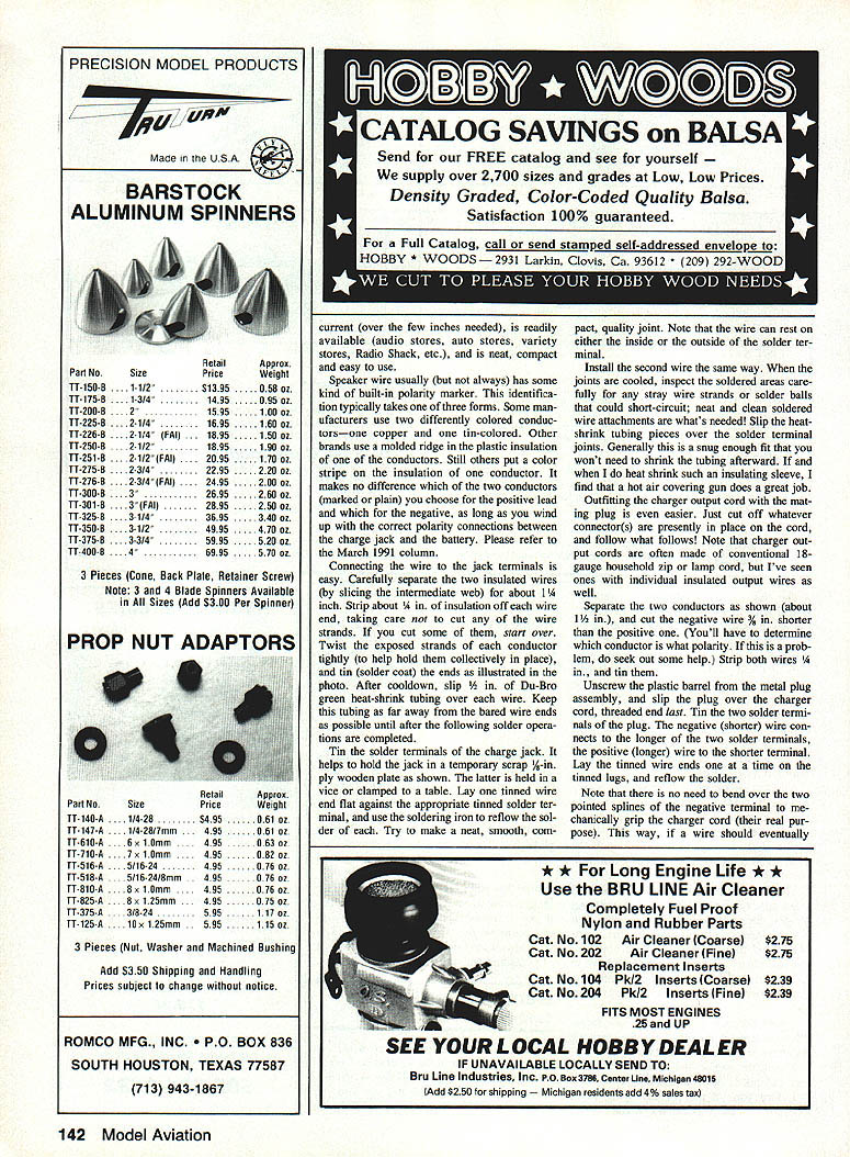
(Last‑minute space considerations forced us to omit the following illustration details in February: expose the ends of the conductor wire strands, twist them and tin them with a 20–30 watt soldering iron as shown; feed electronic‑grade solder to the wire/tip interface until the wire end is fully coated. Tinning the jack terminal is similar. The jack is temporarily held in a 1/8‑in. plywood plate; the positive terminal lug is shown being heated, the negative terminal is left. Cut off the third lug at the 12 o'clock position if unused.)
Astro charge jack and mating plug: the jack (Part No. 4030) mounts in a 5/16‑in. round hole. The mating plug (Part No. 4029) costs about $2.50. To solder the wire to the jack lug, lay the tinned wire end against the tinned lug, heat the joint and reflow the solder; let it cool. Slip previously installed Du‑Bro green heat‑shrink tubing over the wire‑lug joint for a neat finish.
Fuses
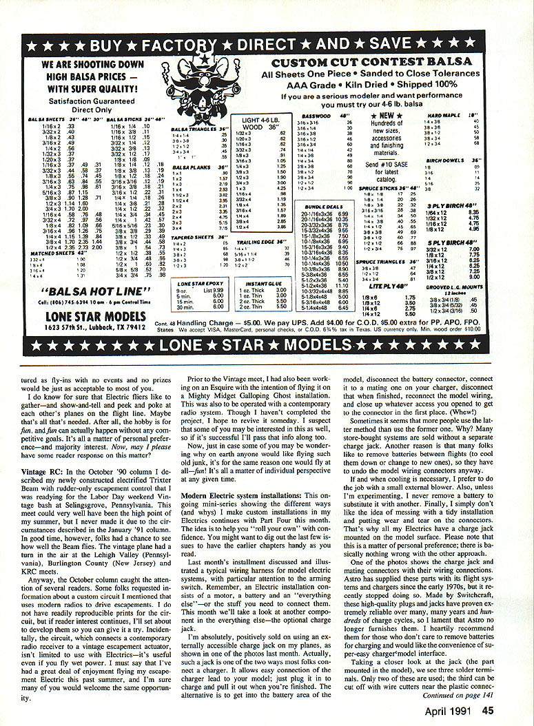
As I have in previous columns in this series, I strongly encourage you to fuse all your electric installations. Three different styles of connectors for ATC‑style auto fuses are shown in one of the photos. This is the only type of fuse I use for electric models and hence the only one I'd recommend. Being flat and plastic‑centered, it's functionally and mechanically much more suited to our purposes than the classic tubular glass‑bodied type used for decades in auto and electronics applications.
Three styles of fuse connectors are shown in the photo:
- Slip‑on style connectors: the simplest, with wires emerging at right angles to the fuse terminals.
- Ready‑made wiring harnesses: cut from store‑bought wiring harnesses; convenient but sometimes bulky.
- Single molded fuse holder‑connector: cut from a ready‑made electric wiring harness; this is my least favorite. These are bulky, the fuse fits too tightly—I've had to apply enormous force to remove a fuse, and when it suddenly jerks free your hands can be burned or injured. Also, the preinstalled short stiff wires aren't best for custom installations.
I recommend the flat ATC‑style fuse in an appropriate holder and avoiding the tightly fitting molded holders.
More next month.
At the personal level
I offer another sincere thank‑you for your many warm and sympathetic cards, notes and letters in reaction to my January column. Today is December 29, and I'm still receiving mail from kind and thoughtful readers. The warmth and encouragement you've shown me and my daughters will be remembered.
I also apologize again for my lack of response to reader letters over the past half year. I hope and intend to resume answering mail in the near future. If you've written and received no reply, please forgive me and bear with me. Mail will be slow. I know I'll never be able to catch up with all the past mail, but I will try hard—soon—to accommodate incoming mail.
Although it has been building season here in eastern Pennsylvania for quite a while, I haven't built anything new—further indication that my personal situation is far from normal. In effect, I'm well behind where I'd normally be with hobby‑related things and many other things in life as well. Much has suffered. If you are wondering what this is all about, please see the January 1991 column.
Happy, quiet landings, everyone!
Transcribed from original scans by AI. Minor OCR errors may remain.

