
Radio Control: Electrics
Bob Kopski 25 West End Dr. Lansdale, PA 19446
This month's topics
- The Electric Connection Service
- Reader mail
- Electric meets
- Electric installations — Part Five
The Electric Connection Service
The Electric Connection Service includes three modelers this month:
- Mitchell Chin
19 Stephens Rd., Tappan, NY 10983 Telephone: 914/365-3455 Mitchell tells me he's most interested in .035–.05 direct and geared motors and likes to modify motors for his scratch-built models.
- Dick Hinckle
6406 E. 140th Terrace, Grandview, MO 64030 I misfiled Dick's letter, so I can't elaborate other than to say he's interested in connecting with anyone else who's flying electrics.
- Pete Williams
1033 Dresslerville Rd., Gardnerville, NV 89410 Pete is hoping to connect with "kindred spirits" in the Carson City / Minden / Gardnerville area (about 45 minutes south of Reno, NV).
If you live in or near these locations and fly electrics, please get in touch with these modelers and share the joy of electric flight. Tell them "Bob sent ya!"
Reader mail
Reader mail continues to arrive in response to the January 1991 column. I never imagined my personal comments in that issue would generate such an overwhelming response. Thank you all for your continuing warmth, friendliness, thoughtfulness, kindness, encouragement, understanding and sympathy.
A number of readers apparently haven't seen my recent columns. For many months I have not been responsive to letters seeking electric help, and I've mentioned this several times in prior columns. Still, many continue to write, and my stack of unanswered mail continues to grow.
Good news: I'm starting to make progress. I've recently been able to answer some of the currently arriving mail, and it is my intent and hope to be fully responsive again. To help me do that, please enclose a self-addressed, stamped envelope (SASE) when you write. I regret that I cannot catch up with the backlog of mail that accumulated since last July; I ask for your understanding and forgiveness if your earlier mail went unanswered.
Electric meets
- Santa Clara County Model Aircraft Skypark — Second Annual All-Electric RC Carnival Fly-In
Scheduled for Saturday and Sunday, June 15–16. Last year's one-day event drew 27 participants and about 60 aircraft. This year's two-day format should attract more participants. The meet is still in the planning stages; write for firmed-up times and full information: Contact Bob Ortman, 631 Sobrato Way, Campbell, CA 95008. Tell him "Bob sent ya."
- 1991 KRC Electric Fly-In
Referred to by other columnists as the premier electric meet. Scheduled for September 21–22 at the Buc-Le Aero Sportsmen field, Quakertown, PA (about 30 miles north of Philadelphia). The 1990 meet drew 135 participants and nearly three times as many planes. Coverage of the 1990 meet appeared in Model Aviation (January 1991) with additional photos in the February and March issues; other coverage appeared in RCM and related publications. A fully detailed mailer can be obtained by writing to the meet organizers.
Electric installations — Part Five
Previous segments of this series discussed connectors, arming switches, battery wiring, charger connections and fuse connections, and included photos of soldering operations, wiring diagrams, and more. As promised, this month's column illustrates fuse installation in detail, updating and improving on information presented in the March 1988 issue.
Materials
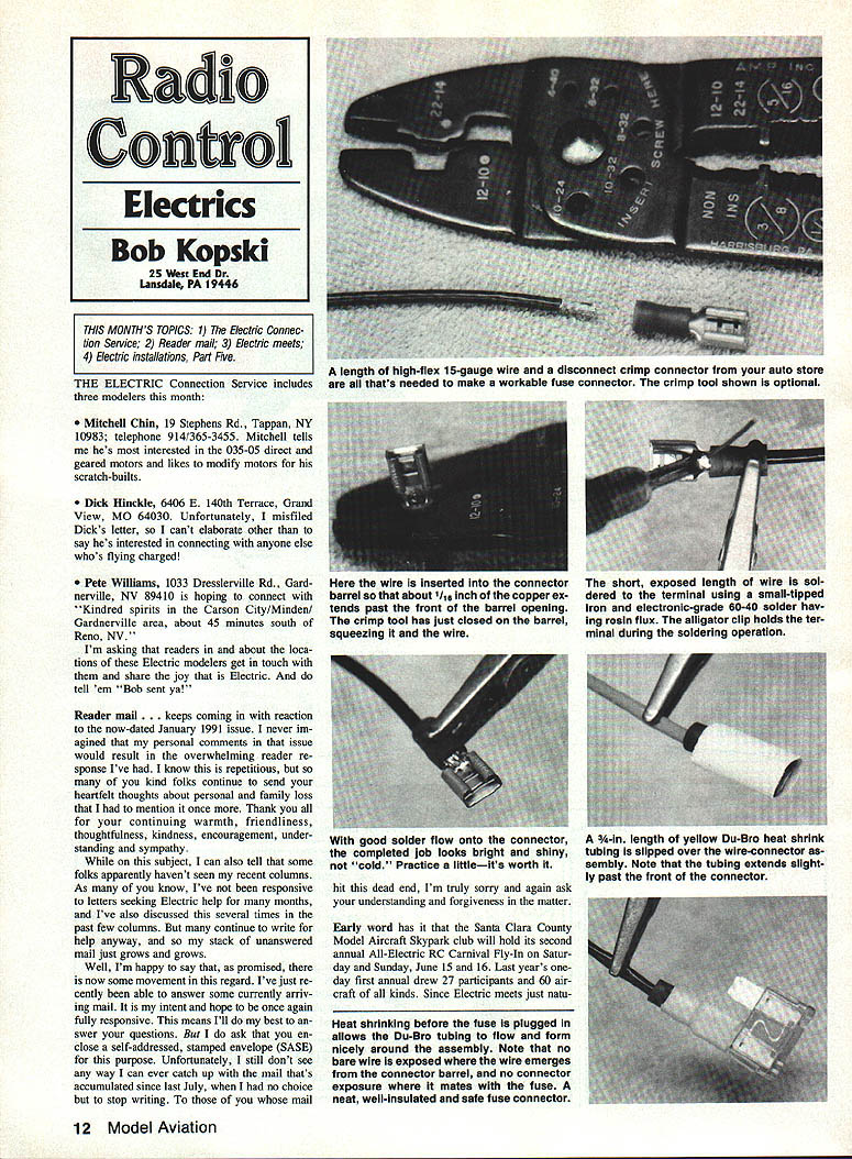
- High-flex wire (hundreds of very fine strands) — I use 14-, 15- or 16-gauge for most installations. Sources include Astro, Jomar, SR and CS Flight Systems.
- 1/4-in. crimpable female disconnect terminals (ATC-style) — available at auto supply stores. For 14–16 gauge wire these are typically color-coded blue.
- Small crimping tool (optional but useful) — jaws are color-coded or stamped for matching connector sizes.
- Soldering iron (20–30 W) with a small tip (about 1/8 in.).
- Electronic-grade solder.
- 1/4-in.-diameter Du-Bro heat-shrink tubing, 3/4 in. lengths (size-coded yellow).
- Alligator clips/third-hand support for holding parts while soldering.
Preparing the wire and connector
- Strip 1/4 in. of insulation from the wire, being careful not to nick any strands.
- Twist the strands neatly with your fingers.
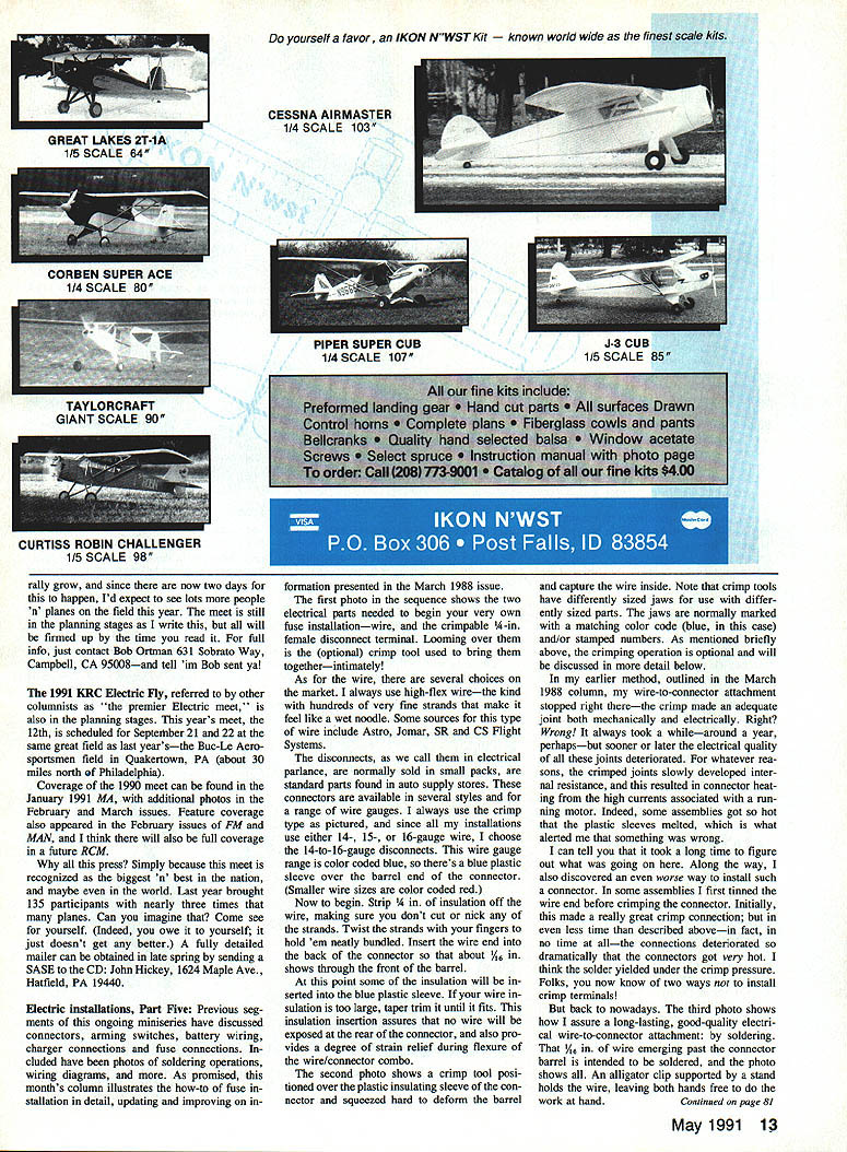
- Insert the wire into the back of the connector so about 1/16 in. of conductor shows through the front of the barrel. Some insulation will be pushed into the plastic sleeve; if the insulation diameter is too large, taper or trim it so it fits. This ensures no bare wire is exposed at the rear and provides some strain relief.
Crimping
Position the crimp tool over the plastic insulating sleeve and squeeze hard to deform the barrel and capture the wire. Crimp tools have differently sized jaws for different connector sizes (matching color codes and/or numbers). The crimp provides good mechanical attachment but, by itself, may not provide a lasting low-resistance electrical connection.
Problems with crimp-only and pre-tinned wire crimping
- Crimp-only joints can develop increased internal resistance over time, causing heating under high motor currents. In some cases the plastic sleeve can melt.
- Tinning the wire before crimping initially looks excellent but tends to fail even faster; the solder may yield under crimp pressure, leading to poor connections and heating.
Soldering the joint (recommended)
To assure a long-lasting, reliable electrical connection, solder the joint after crimping (or instead of crimping if you prefer):
- Tin the wire end and the connector barrel. Use a 20–30 W iron and electronic-grade solder. Alligator clips on a stand make holding the parts easy.
- Bring the iron into contact with the exposed copper wire and apply solder so it flows smoothly over the copper and onto the connector metal. Make sure the solder wets the connector but do not allow solder to flow into the area where the fuse blade will seat.
- The solder bead should be smooth and shiny when finished.
I have not had problems with the plastic sleeve melting during soldering when using good technique and a quick job, but results may vary with connector brands.
Heat-shrink and final fit
- Slip a 3/4-in. length of 1/4-in.-diameter Du-Bro heat-shrink tubing (yellow) over the connector end so it extends slightly past the open end of the connector.
- Heat the tubing with a heat gun, rotating the connector so the shrink fits evenly. The tubing should flow-fit over the connector.
- Plug the fuse into the connector and check mechanical fit. Different connector brands vary; a tight fit is important. If the fit is loose, gently squeeze the connector "curl" to tighten it (easier before heat-shrink, but can be done afterward). After several insertions/removals the fit may loosen and can be tightened slightly with pliers—do this only if the connector assembly is thoroughly soldered so mechanical and electrical integrity remain good.
This fuse-to-connector joint is likely the weakest connection in your installation. Unlike servo connectors, ATC fuse connectors are of noticeably poorer electrical and mechanical quality, so prepare the assembly carefully.
Fuse as an arming switch (caution)
Some people use the fuse as a removable arming switch — leaving the fuse out until flight time and plugging it in to arm the system. I consider this questionable because the connector fit loosens with repeated use. The fuse is intended as protection when needed, not as a frequent-use arming device. I welcome reader feedback if you have had success with this practice.
Optional crimping and solder-disconnects
- Crimping is useful for mechanical attachment. Soldering provides the reliable electrical connection. If you lack a crimping tool, soldering can serve both purposes, but you will need clamps to hold the parts during soldering.
- Solder-connectors (connectors without the plastic sleeve meant to be soldered) are tempting, but I prefer the plastic-sleeved connectors for strain relief and insulation. I also prefer to solder only at the wire end so the wire remains flexible where it enters the connector barrel — wicking solder under the insulation would eliminate that flexibility. The plastic sleeve also enlarges the barrel and makes it easier to apply heat-shrink tubing.
Closing
You're now set to do a quality fuse installation in custom wiring or in a store-bought wiring harness. Review the March and April "RC Electrics" columns for related discussion before you begin. I'll bring more on electric installations in next month's column. In the meantime, have a happy electric springtime, everyone!
Transcribed from original scans by AI. Minor OCR errors may remain.

