
Radio Control: Electrics
Bob Kopski 25 West End Dr. Lansdale, PA 19446
THIS MONTH'S TOPICS
- The Electric Connection Service
- NJ Electric Meet
- Reader Reaction — "Events"
- Charging Tip
- Electric Installations — Part Seven
THE ELECTRIC CONNECTION SERVICE
The Electric Connection Service has two offerings this month.
- Everett Wick
4765 Willowview Rd., Dayton, OH 45439 Tel. 513/859-8594 Everett would very much like to connect with other electric enthusiasts in the Dayton area and is interested in the possibility of forming an electric club. If you are considering the same, I recommend Bob Aberle’s May 1991 article in Flying Models about SEFLI (Long Island). It has useful ideas beyond that specific club.
- Jef Raskin (yes, one "f")
Gypsy Hill Road, Box 1638, Pacifica, CA 94044 Tel. 415/359-8588 Jef is editor of the San Francisco Vultures newsletter. The Vultures have flown since 1939. Jef is enthusiastic about Midwest Electric HOTS and lives close to some good flying fields; he invites anyone in the Bay Area to contact him about electric flight activities.
Also in the connection service this month:
- Bob Afflerback
123 Harrington Circle, Willingboro, NJ 08046 Tel. 609/871-8777 A former glow-power pattern flier who is now a full-time electric flier and editor of Flying Models' monthly electric column. Bob reports the annual BCRC/CC fun-fly on July 13 at North Burlington Regional High School (a bit south of Bordentown, NJ). Contact Bob for full info.
If you or your club (or club-to-be) would like to electrically connect with others in your area, send your info and I’ll present it here in Model Aviation. Please be patient—it can take a few months to appear.
READER REACTION — "EVENTS" — AND MORE
Reader response to the request for input on electric events was strong. The reactions fell into two main preferences:
- Casual, low-pressure, fun activities/events.
- No formal events at all; gatherings that emphasize sharing and the freedom to fly.
Many readers pointed out that "fun" events needn’t be competitive, and that the word “contest” evokes an overzealous image many electric modelers don’t want. From mail and observations at KRC and other meets, the overwhelming majority favor non-killer, pressure-free events. At the same time, some readers note that electric modelers are skilled craftsmen and pilots who sometimes get underestimated.
One reader suggested that some of the more competition-oriented electric builders and pilots should mix it up with glow (wet) flyers by flying electrics against wets in the same formal AMA events—rules don’t rule this out. This reader was Bob Benjamin of PSEMF in Washington State; he described his participation in last year’s US Scale Masters Championships flying an electric Porterfield in the April 1991 MA. Bob will also have a construction article coming up for his Tigerkitten E aerobatic design.
Teamed Events — WESS Example
Neil Rossi, president of the Westmoreland Electric Soaring Society (WESS), reported an innovative combined electric/soaring event. WESS teamed with two local glider clubs (the Steel City Soarers and the Tri-State Soaring Society) to run two-man teams: one soaring pilot (winch-launched sailplane) and one electric pilot. Teams competed using a simple point system; teammates helped each other with timing and tasks. On August 25 the five teams flew tasks such as two-minute duration, a 25-minute sealed-envelope duration, ten-minute duration, and spot-landing bonus points.
Important: the sailplanes and electrics were not competing against each other — teams competed. This cooperative format blends disciplines and skills and could be extended in many ways (teamed wet/electric aerobatics or other teamed events). Since many electric modelers reject the classic heated contest format, creative teamed or cooperative event formats may be attractive alternatives.
Other Reader Reactions
- The escapement driver circuit used in my Vintage Trixter Beam to allow modern radios to activate an old escapement drew interest from those who trace their RC origins to the vintage era. I may attempt to collect and publish how-to information later, time permitting.
- The ongoing Electric Installation mini-series has been well received and will continue for several more issues.
- A reminder about correspondence: I try to be responsive, but some inquiries require substantial research. Please include a SASE if you want a reply, and write legibly to save time.
CHARGING TIP
Electronically controlled chargers (those with voltage boost circuits and/or peak detectors) can be affected by signals from an RC transmitter. If you observe a current meter wandering when it should be steady, or other odd behavior, check whether a transmitter is on and within a few feet of the charger, its cord, or the pack under charge. This is interference. Turn off the transmitter and continue charging — and your fellow fliers on the same channel will appreciate it.
ELECTRIC INSTALLATIONS — PART SEVEN
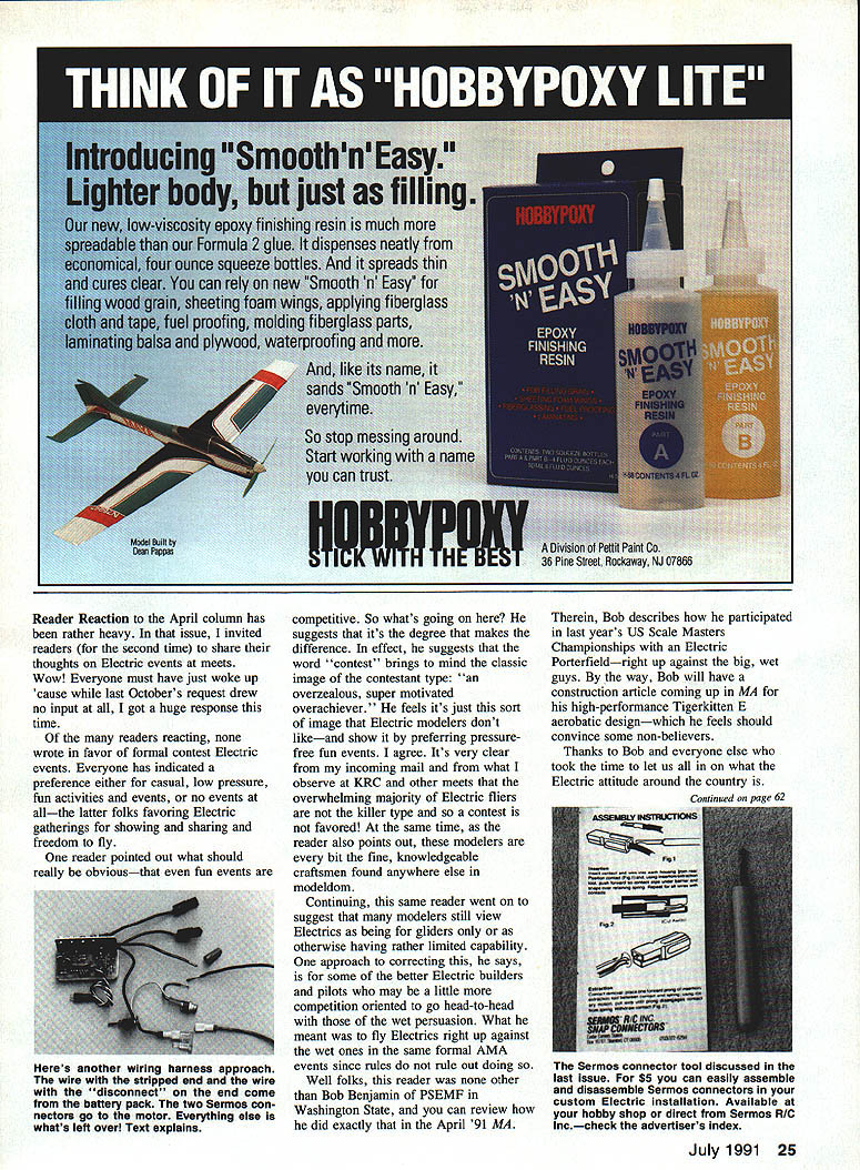
This month’s installation example is a wiring-harness variety in which an older Jomar SC-4 speed control is hard-wired (permanently connected) to an arming switch, charge jack, and fuse. The assembly is effectively a removable module that can be swapped from plane to plane and represents the “everything else” between motor and battery.
Key features of this example:
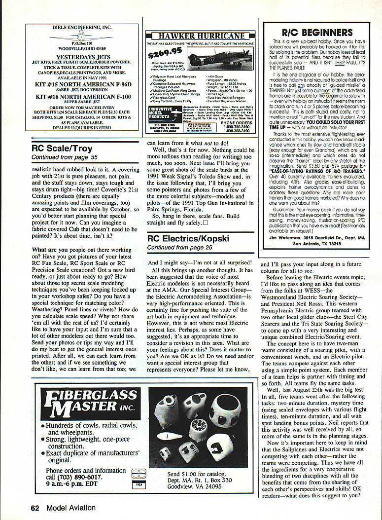
- Mounting: The bottom of the speed-control PCB has double-stick Velcro attached to mate with Velcro in the model.
- Connectors: There is only one set of servo-style connectors — on the speed-control output leads that interface with the motor. The speed-control positive input lead is soldered directly to the arming switch (no connector in that path). The arming-switch input is the system fuse output (as shown in earlier installments). The positive charge-jack lead is also connected to the switch terminal. The unconnected lead shown elsewhere is the positive lead from the battery.
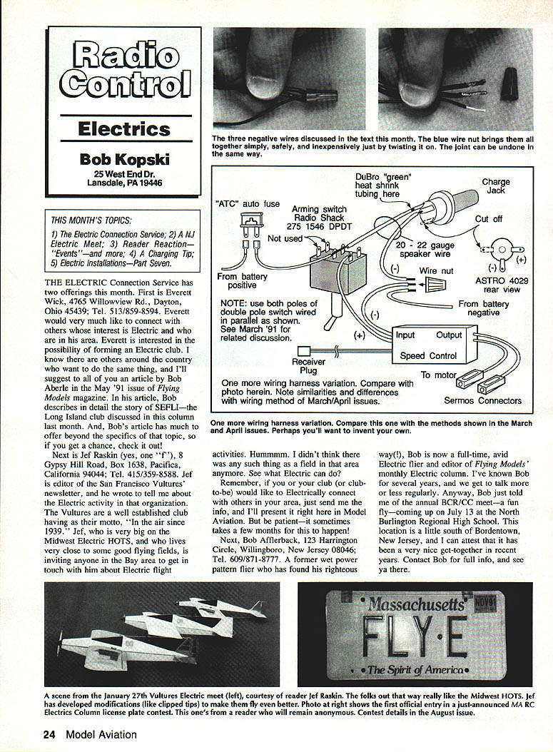
- Negatives tied with a wire nut: The battery negative, the charge-jack negative, and the speed-control negative input need to be connected together. In earlier examples these were tied on unused arming-switch terminals; here they are joined using a small wire nut (blue size). Strip about 3/8 in. of insulation (do not cut strands), lightly twist the wires together, then screw on the wire nut.
- Wire sizes: High-current wiring is high-flex 14–16 gauge. Charge-jack wires are 20–22 gauge insulated single conductors (speaker wire works well; see the March MA discussion).
- Arming switch: The pictured switch is SPST (single pole, single throw), which I no longer use in new installations. I now prefer a double-pole version to better isolate circuits.
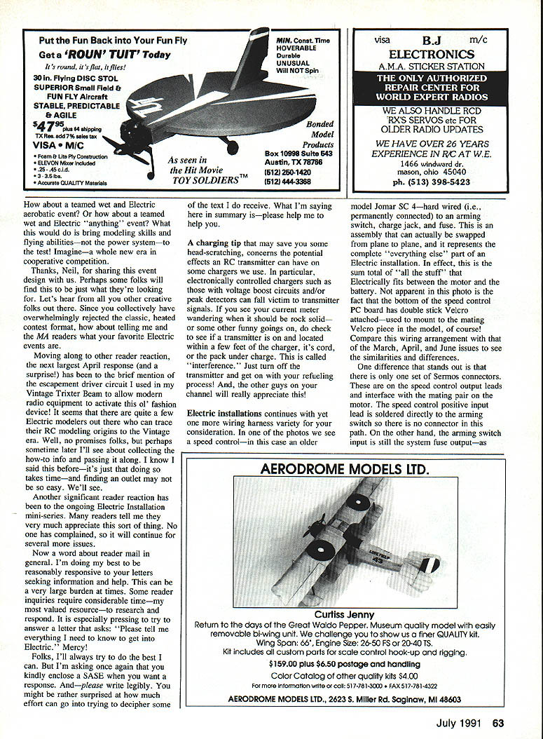
- Modular vs. unitized: Most newer models keep the speed control modular with removable connectors on both input and output for easy swapping and testing. The unitized (soldered) harness shown here appears in many earlier models. Both approaches are workable; choose what fits your needs.
The goal of this mini-series is to present a variety of wiring options so you can select—or create—a harness best suited to your model and preferences. Every installation has a motor, a battery, and an “everything else” area where you can customize.
So much for another month. By the time you read this, the country should be well past the winter blues and into the sky blues.
Happy, Quiet-Power Landings, Everyone!
Bob Kopski 25 West End Dr., Lansdale, PA 19446
Transcribed from original scans by AI. Minor OCR errors may remain.

