
Radio Control: Electrics
Bob Kopski 25 West End Dr. Lansdale, PA 19446
THIS MONTH'S TOPICS:
- Beginners: How to Write a Letter
- The License Plate Contest
- Electric Installations—Part Eight
- A New Connector Announcement
Beginners: How to Write a Letter
Last month's column included comments regarding reader letters wherein the thrust was to "help me help you."
Among other things, I poked some fun at one common kind of letter—the "please tell me everything I need to know to get started" kind. I hope my point got across—it's not a letter that's needed here; rather it's more like the Third Testament! But let's pause for a while and consider this always-genuine inquiry.
Despite the fact that volumes have been written in this and other magazines—not to mention several books on the subject—there are always new folks getting interested in both modeling and Electric, and all the references just mentioned are history—i.e., probably unknown to new readers. Of course, like any columnist, I'm all for helping these folks get started, but responding to such a wide-open request is a BIG job! Given this, I'd like to offer some suggestions to folks who really have this all-encompassing question to ask. Of course I'm well aware that future new readers will not necessarily benefit from the following morsel of wisdom since it, too, will soon become history!
It is very helpful to me to know more about you and your interests as I develop a response to your "everything" question. For example—are you an experienced modeler, or do you think that "glue" is some computer part? Many readers, it turns out, have never built anything, and I'd be inclined to respond quite differently to these folks than to the "I've been building gas jobs for 40+ years" folks. Then too, building is one thing; flying is something else, so a comment about your experience, if any, in this regard is helpful to me as well.
Next, I'd like to know what model type appeals to you. For example, some readers like OTs, some sailplanes, and some experienced pilots want something "hotter" to try Electric on. Some just want planes. So tell me! And I'd also like to know if you have a budget or target investment level in mind. Then there's a sort of obvious question—does anyone else in your area or club fly Electric?
Now, what about the local hobby dealer? Does he carry anything Electric? Does he even know how to spell E-l-e-c-t-r-i-c? Or is he the very reason you're writing for help? You might be surprised at how many readers get nothing but discouragement from the local shop when it comes to Electric. This, by the way, is becoming one of my favorite pet peeves. To all you not-quite-up-to-date hobby dealers out there: it's time to recognize that Electric is a force of the present and a major force in the future of Modeldom. If you lack familiarity with the topic, start reading! And give it a try yourself. I'm convinced that Electric will grow to become a major part of the hobby business—your business.
But back to helping newcomers. Remember my point here—"help me to help you." Keep your letters to the point—but include all the points. I'll do my very best to help you get started in whatever way I can. Of course, please also include a SASE!
The License Plate Contest
A contest of a different kind was subtly announced last month. If you missed it, go back and check out the photo of the "FLY E" license plate submitted by a Massachusetts reader. He was reacting to my own offering in this issue one year ago—a photo of my proud "E-FLIGHT" vanity plate and my challenge to you "to be the first in your State..." Anyway, having received this first reader photo, I decided to run my own (sorta) contest and invite and encourage all readers to develop their own personalized, creative vanity plates designed to spread the Electric word.
Send me a photo of your plate. Then, in some future column, I'll present all the pictures I receive, and you readers can vote for your favorite. The plate getting the most reader reaction wins. Realizing that all this will take some time, your photo submissions can be made up to Dec. 31, 1992. Then it will take a few months to publish the photos and receive reader reaction. All pix become the property of this columnist, and none will be returned.
The more submissions the better, of course. Remember, we're spreading the Electric word this way—everywhere we drive! (Do drive in front of "those" hobby shops a few times!) I'll print a reminder of this long-term competition every now and then. Of course, my plate is not eligible (I have lots of Skyvolts!) and the FLY E plate of last issue will be repeated when the time comes. Now—why am I doing this? Because I believe in Electric—a major part of Modeldom's future!
(Hobbies Skyvolt kit — see MA, 1/90.)
Electric Installations — Part Eight
Electric installations continue this month with an offering prompted by a reader's letter. This recent letter posed the question of how to best install Sermos connectors. The writer explained that he always has difficulties with soldering and cannot seem to get a quality joint. As I read and then tried to respond to this letter, I realized two things. First, his problems seemed to center on the soldering, and not on the Sermos connector per se. Second, this is a tough question to answer without pictures to replace the many, many words needed! Thinking that others may have questions in kind, I'm now offering the following.
There are several prerequisites for good soldering but in general they all fall into two categories: tools and technique. The former is rather simple to deal with. The latter is rather simple to deal with! The former requires a few dollars; the latter a little practice.
#### Tools
While this column will address the Sermos connector as an example, most Electric modeling wiring requirements can be met with one soldering iron. The one iron needed is a 25- to 35-watt iron with about a 1/8-inch chisel tip. One example is the ACE catalog No. 32K7760 Ungar handle, the No. 32K12355 element, and the 32KPL113 tip. A good buy in a broad-based soldering capability are two irons—the Heath catalog No. GDP-3125 and No. GDP-3140 irons and top assortment GDP-3100. More on these things in the future.
Irons to avoid include those with a cone-shaped tip, irons with uncoated copper tips, and soldering guns. Soldering tips that are clad with iron and/or silver plating are my favorites, and I strongly recommend these. Soldering guns are not well suited for our purposes in that they are harder to handle, don't have good tip shapes, and generally get too hot and have too little thermal mass. While soldering guns do have limited applications, I own several and virtually never use them!
It's also necessary to use the right solder. I always use 60/40 of small diameter and with built-in electronics-grade flux (not acid). An example is Radio Shack No. 64-005. This solder is 0.032 inch diameter. But my real all-time favorite is Ersin Multicore—either SN 60 or SN 62 of comparable diameter. This brand is always my first choice—though harder to find.
#### Technique and Fixture
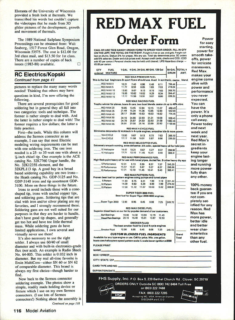
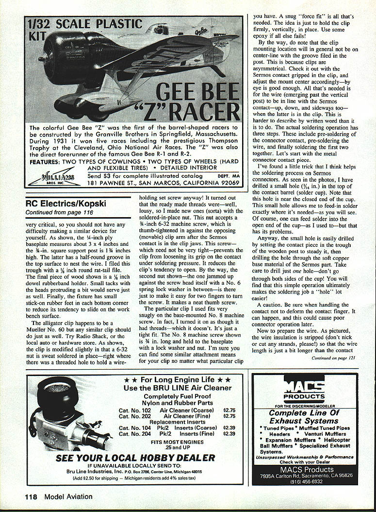
The photos show a simple, readily made holding device or fixture which I use on my own Sermos connectors. Nothing about the assembly is novel, but the fixture simply makes the job easier and more consistent. The Sermos plug body is supported on the lower portion of the fixture and the center post is held by the top screw. The solder contact is formed on a small piece of brass that clamps the wire in place. The wire is routed in a small trough and held by a rubber band while the soldering is done. The thumb screw presses the brass contact against the wire so that the iron and solder may be applied to form the joint.
The baseplate is 1/4-inch ply and measures about 3 x 4 inches. The 3/8-inch square support post is 1 1/4 inches high and has a half-round groove in the top surface to nest the wire; I filed this trough with a 1/8-inch round rat-tail file. The final piece of wood shown is a 5/8-inch dowel rubber-band holder. Small tacks with the heads protruding a bit would serve just as well. Finally, the fixture has small stick-on rubber feet in each bottom corner to reduce its tendency to slide on the workbench surface.
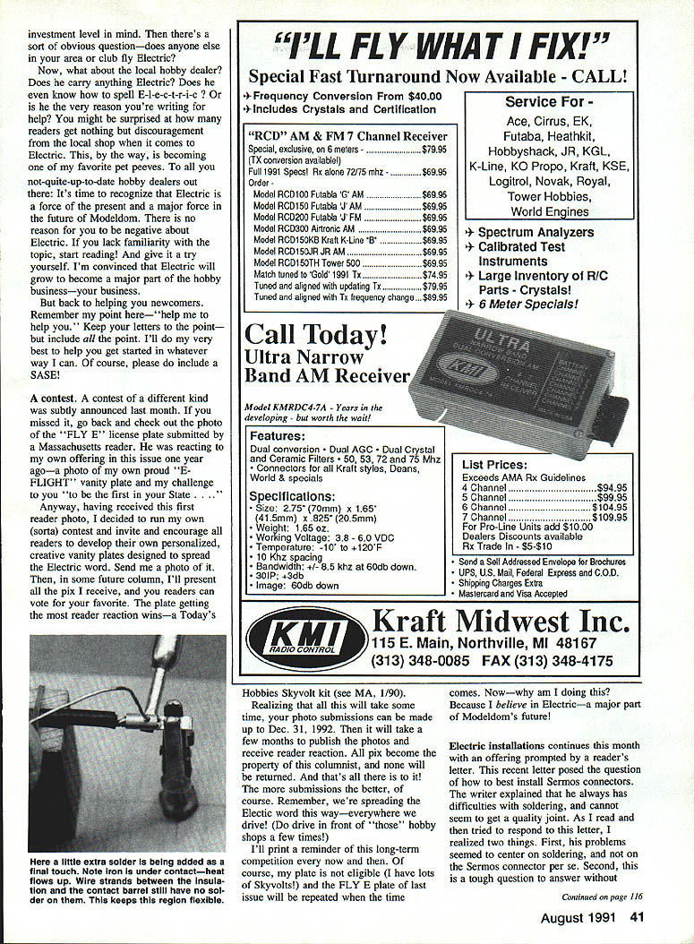
The alligator clip happens to be a Mueller No. 60 but any similar clip should do just as well. Try Radio Shack, or the local auto or hardware store. As shown, the clip is modified slightly in that a 6-32 nut is sweat-soldered in place—right where there was a threaded hole to hold a wire-holding set screw anyway. It turned out that the ready-made threads were—well, lousy, so I made new ones (sorta) with the soldered-in-place nut. This nut accepts a 3/16-inch 6-32 machine screw, which is thumb-tightened in against the opposing (movable) clip arm after the Sermos contact is in the clip jaws. This screw—which need not be very tight—prevents the clip from loosening its grip on the contact under soldering pressure; it reduces the clip's tendency to open. The second nut jammed up against the screw head itself, with a No. 6 spring lock washer in between, makes a neat thumb screw that's easy to turn.
The particular clip I used fits very snugly on the base-mounted No. 8 machine screw. It's just a tight fit. The No. 8 machine screw shown is 3/4 inch long and held to the baseplate with a lock washer and nut. A snug "force fit" is all that's needed. The idea is just to hold the clip firmly, vertically, in place. Use some epoxy if all else fails!
Note that the clip mounting location will in general not be on center-line with the groove filed in the post. This is because clips are asymmetrical. Check it out with the Sermos contact gripped in the clip, and adjust the mount center accordingly—by eye is good enough. All that's needed is for the wire (emerging past the vertical post) to be in line with the Sermos contact—up, down, and sideways too—when the latter is in the clip.
#### Soldering Steps
The actual soldering operation has three steps: pre-soldering the connector contact, pre-soldering the wire, and finally soldering the wire to the contact. Let's start with the metal connector contact piece.
I've found a little trick that helps the soldering process on Sermos connectors. Drill a small hole (1/16 inch) in the top of the contact barrel (solder cup). Note that this hole should be near the closed end of the cup. This small hole allows me to feed solder exactly where it's needed. Of course, one can feed solder into the open end of the cup—as I used to—but that has its problems. The small hole makes the soldering job a whole lot easier.
A caution: be sure when handling the contact not to deform the contact finger. It can happen, and this could cause poor connector operation later.
Now to prepare the wire. Strip the insulation carefully—don't nick or cut any strands—so that the exposed wire is just a bit longer than the contact. Keep the portion of the wire near the insulation solder-free and smooth; this region should remain flexible.
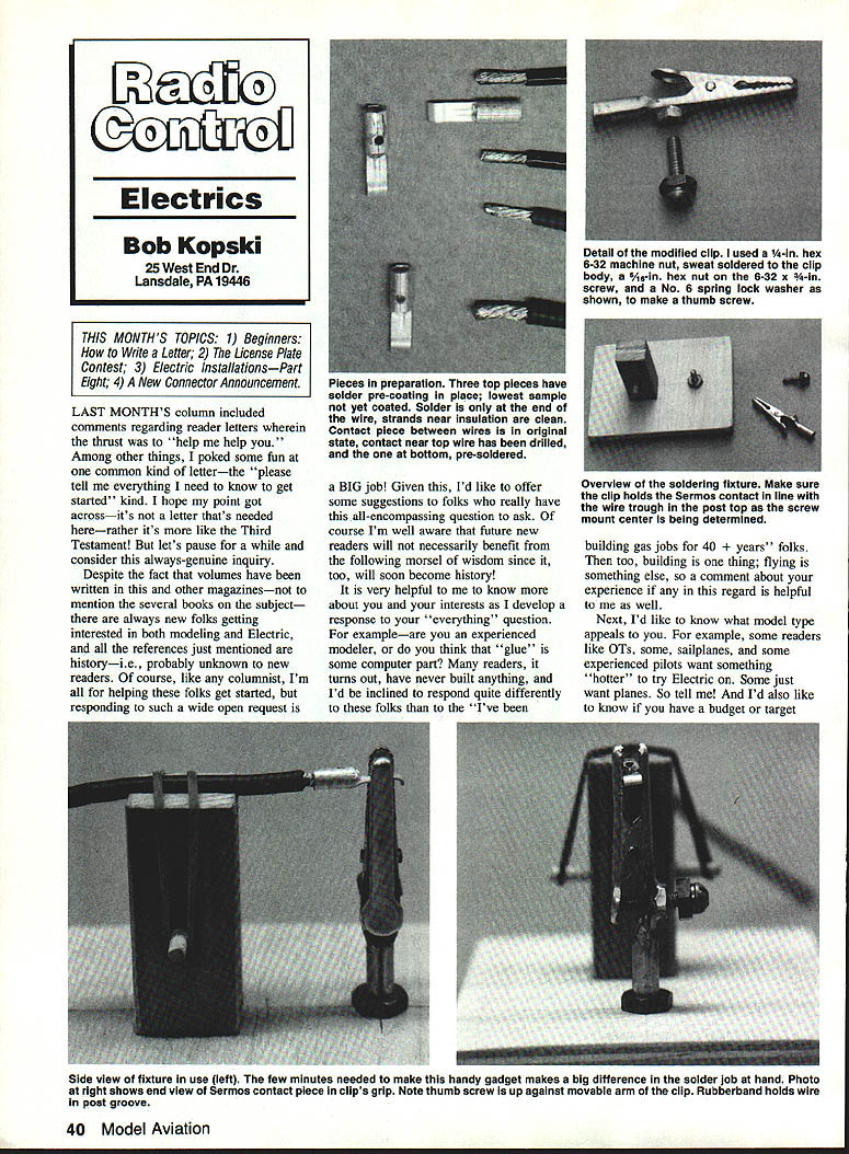
Pre-tinning of the wire strands near the insulation end is important. Clean the wire strands, tin them lightly, and then place them in the trough. Pre-tinning the contact piece is also helpful. Heat the contact with the iron and apply a little solder to form a fillet. Then bring the pre-tinned wire into position, heat briefly and let the two solders flow together to form a good mechanical and electrical joint.
With the drilled hole in the contact, feed solder into that hole—about 1 to 1 1/4 inches of solder is about right—allowing the solder to melt as you feed more in place. Let the molten solder collect inside the closed end of the solder cup so the solder puddle will be where the pre-coated wire end will sit when the two are brought together.
With the iron still held in place to keep the solder molten, feed in the wire and allow it to bottom at the closed end of the cup. Allow time for the wire solder pre-coat to flow. If appropriate, feed some additional solder into the drilled hole. Once again—do not allow the solder to wick back along the wire to the insulation. Remove the iron and allow the assembly to cool. Give it enough time before moving anything. Loosen the thumb screw, squeeze the clip, and release the contact. Presto—one great Sermos contact installation by your very own hands!
Keep soldering time to a minimum. Excessive heat can damage insulation and the connector body. Short, firm contact with a properly tinned tip will do the job. If you need more heat, use a heavier iron or preheat the parts a little, but avoid long contact times.
After soldering, clean the joint with a solvent to remove flux residue. I use acetone and a throwaway hardware-store "acid" brush (or ACE "oxy brush" — Catalog No. 224L050)—scrubbing the contact surfaces clean of any such residue. This is important for good contact operation. Don’t scrape the surfaces or you’ll risk damaging the silver plating—just use the solvent and a brush, and then wipe dry with a tissue. Inspect the joint for a bright, shiny appearance—dull joints are suspect and may be cold joints. A good solder joint should be mechanically strong as well as electrically sound.
Soldering problems are usually caused by poor surface preparation, insufficient heat, using the wrong solder, or using improper tools. Address these areas and most soldering troubles disappear.
I'll have more on soldering other things in the future. Meanwhile, here’s hoping this has been of some help.
Late News — New Connector Announcement
As I was writing this column, my first pieces of the long-awaited new Astro connector sets arrived at my door! They are a compact assembly employing rather large gold-plated contacts in a compact plastic housing. I'll have more details next month including photos and data.
Here's wishing you all a happy, quiet, safe Electric-flyin' Summer!
Transcribed from original scans by AI. Minor OCR errors may remain.

