
Radio Control: Electrics
By Bob Kopski
Twofers this month. I’ll cover two topic areas. First, a discussion and comparison of several “large” motors—there’s comparatively little information readily available on this subject, and I hope this coverage will prove useful to those considering moving up in power system size. Second, Basic Electricity, Part 2 picks up where last month’s installment ended. This is a continuing short course aimed at simplifying the confusing science stuff.
Large motors
It’s no secret that many who first try electrics use comparatively small-size power systems. That makes sense: it’s the lowest-cost way to discover how much fun electrics can be. Smaller systems are easiest to charge and can provide surprisingly high performance. I’ve maintained that small systems can provide about as much “performance” as large systems, and that’s why I favor electric competition classes based on size, at least for now.
Nevertheless, there are reasons to consider larger power installations. Larger models can be heavier and may handle poorer weather better; they often ground-handle more predictably. Although larger installations cost more and are harder to charge, many pilots find the “biggies” more fun.
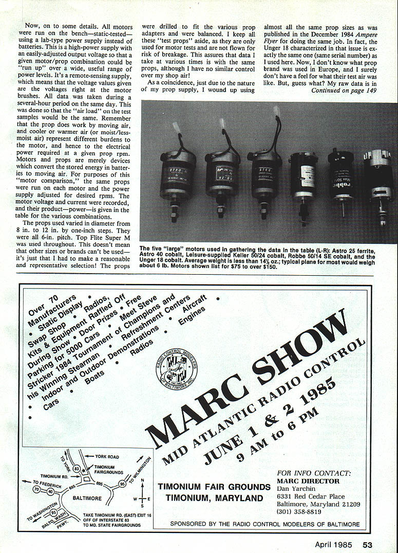
The lead photo for the original article shows six motors of about the same apparent size. “Motor size” is a confusing term because there is no established standard; I categorize motors by how much power a product will handle. Anyone who’s followed MA’s electric articles (beginning September 1983) knows I favor relating electrical power to model parameters. In other words, a model that’s “so big” and weighs “so much” needs “so much” electrical power to fly in the desired manner; flight duration is then determined by battery size.
A table included with the original article lists parameters and statistics for the motors used in this presentation. While many more large motors exist, I only had these to test. Six motors (with five propeller combinations each) were tested. One Astro ferrite motor was probably inappropriately included—there’s nothing wrong with it, it was simply smaller than the other five. I plan to retest it along with others closer to its size in the future; meanwhile the results are included for information.
All data are based on a single sample of each motor/prop and are believed correct. “AVR” in the table is the input voltage at the test. Input power is the product of voltage and current (amps). Voltage was varied to obtain desired rpm values. For the most part, prop and rpm set the power level into the motor. All motors ran with about the same efficiency over the ranges shown.
Example use of the data: if you want about 250 watts using a large prop (11x6 in. in the table), the Astro cobalt, Keller, and Unger motors deliver this power at around 8,000 rpm. Examine the listed AVR to determine the required voltage (and therefore the number of cells). For the same amp-hour cells, a motor that runs at higher current/ lower voltage will give shorter flight times than one that runs at higher voltage/lower current. If you like a particular motor but want longer flights, change prop size or add cells as appropriate.
Testing methodology
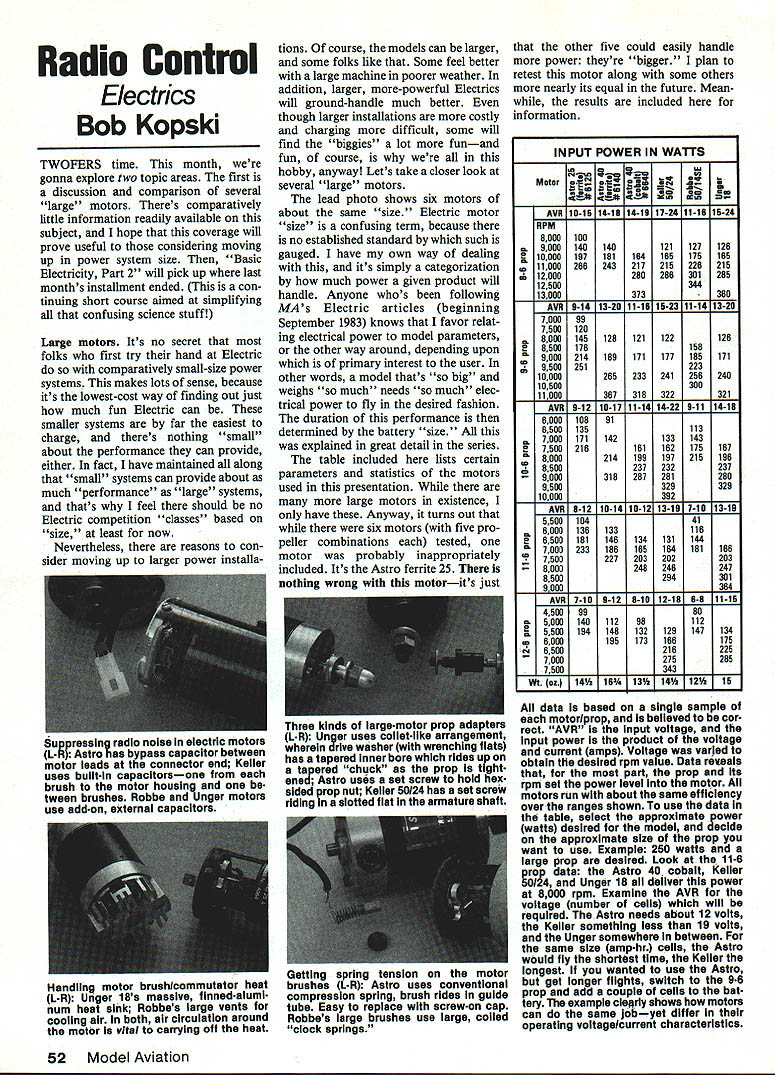
- Motors were bench-tested (static) using a lab-type, high-power, remote-sensing power supply rather than batteries. The adjustable output allowed stepping motors/props over a useful range of power levels while maintaining accurate voltage at the motor brushes.
- All data were taken during a single several-hour period on the same day so air conditions (temperature, humidity) would be consistent. Air density affects prop load and thus the electrical power required at a given rpm.
- The same props were used on each motor; voltage and current were recorded and their product (power) is reported in the table for various combinations.
- Props used ranged from 8 in. to 12 in. diameter in 1-inch steps; all were 6-in. pitch Top Flite Super M. Props were drilled to fit various adapters and balanced. Test props are reserved for bench testing only to ensure consistent data.
- Electrical measurements used digital volt and amp meters (estimated accuracies ±1% and ±2% respectively). RPM was read with an analog tach (accuracy plus resolution about ±2%). Absolute accuracy is less important here than relative results.
Motors were run over load and input power ranges that I would personally use in my planes. My approach is conservative: I want motors, batteries, and systems to run well and last long, so I generally operate below advertised maximums. For practical reasons, I usually don’t test much beyond 20 volts (too many cells to charge is a hassle) or much beyond 20 amps (heavy currents reduce system efficiency rapidly due to IR losses).
You’ll notice not all motors were tested to the same rpm limits with the same props. Often either operating voltage or current reached the upper limit I cared to test. Some motors with large props draw high current at relatively low voltage; others behave inversely because of armature winding design or intended application. In some cases an intermediate prop would let both voltage and current top out simultaneously, producing the highest power points listed. A few missing test points were due to oversight during hectic testing.
How to use the test data and select a motor
The most important consideration is your intended application:
- For low, lazy sport flying: choose a motor/prop that produces the necessary power at relatively higher voltage and lower current. A given battery will then last longer.
- For high-power bursts of short duration (competition): choose a motor/prop that uses the fewest, smallest cells (lightest pack) that still meets the current demand for the desired run time.
- For a compromise (hotter sport flying): choose a motor/prop/battery that can produce high power with reasonable run time and use a quality electronic speed control (ESC). The ESC allows easing off power to preserve battery and extend flight time, then applying full power when needed.
If the table doesn’t contain the exact motor/prop/power point you want, change prop pitch or diameter to move power up or down. Remember:
- Lowering pitch reduces power; increasing pitch increases power.
- Reducing diameter reduces power; increasing diameter increases power.
- If you trim a prop, rebalance it before use.
Within measurement limits and prop suitability, the tests reinforce a key point: it’s the prop that primarily determines the electrical power required from the battery. Cobalt magnets are somewhat lighter and more efficient than ferrite magnets (and cost more), but the differences aren’t usually decisive—choose a motor by the features you prefer: cooling method, prop adapters, mounting requirements, weight, availability, etc. There’s no single “best” motor—choice depends on individual needs and preferences.
Summary — Large motors
The motors characterized perform well and similarly; all will do a good job flying larger planes in the right application. Use the table (and the guidance above) alongside earlier MA electric articles to select a motor/prop/battery combination that meets your desired flight performance.
Basic Electricity, Part Two
Last month’s column introduced simple electrical terms (voltage and current) and analogies with water pressure and flow. Voltage is like the depth of water in an overhead tank; current is like water flow through a pipe. Electrical power into motors is the product of voltage and current: P = V × I (watts). Higher power delivers more work in a given time—more power produces a higher climb rate for a given plane. More voltage requires more cells; more current drains a battery faster. Larger planes generally require motors capable of higher voltage/current to produce higher power.
Let’s consider simple resistive examples.
A flashlight lamp is a small resistance wire which, when connected to a battery, allows current flow. The lamp is the load; battery voltage times the current gives the power delivered to the lamp, which produces heat and light.
A larger example is an electric clothes iron—typical power around 1,000 watts. It takes a lot more power to heat and maintain an iron at temperature than to light a flashlight.
Ohm’s Law relates voltage (V), current (I), and resistance (R). It can be written three equivalent ways:
- Voltage = Current × Resistance
- Current = Voltage / Resistance
- Resistance = Voltage / Current
If two of the terms are known, the third can be calculated.
Example: a flashlight with two cells producing 1.5 V each, connected in series, gives 3 V total. If the lamp resistance is 12 ohms, the current is:
I = V / R = 3 / 12 = 0.25 A (1/4 amp)
If you measure 0.25 A from the battery with an ammeter and measure 3 V with a voltmeter, you can compute resistance:
R = V / I = 3 / 0.25 = 12 ohms
Power (P) is volts times amps:
P = V × I (watts)
Using Ohm’s Law, power can also be expressed as:
- P = I²R
- P = V² / R
Let’s calculate the flashlight lamp power three ways (all yield the same result):
- Using volts and amps:
P = V × I = 3 × 0.25 = 0.75 W
- Using current and resistance:
P = I²R = (0.25)² × 12 = 0.0625 × 12 = 0.75 W
- Using voltage and resistance:
P = V² / R = 3² / 12 = 9 / 12 = 0.75 W
So, whether you use V × I, I²R, or V²/R, the computed power is the same.
That wraps Part Two of the basic electricity short course. These relationships tie directly into motor/battery/prop selection: understanding voltage, current, resistance, and power lets you predict performance and choose systems that meet your flight goals.
Happy Electric landings!
Direct questions (with SASE) to the author: Bob Kopski 25 West End Dr. Lansdale, PA 19446
Transcribed from original scans by AI. Minor OCR errors may remain.

