
Radio Control
Electrics
Bob Kopski
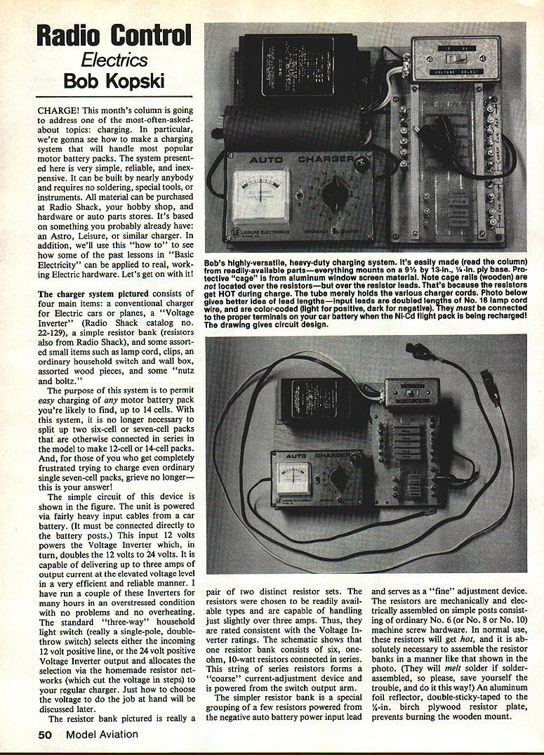
CHARGE! This column addresses one of the most-often-asked-about topics: charging. Here I describe a simple, reliable, inexpensive charging system that will handle most popular motor/battery packs (up to 14 cells). It can be built by nearly anybody and requires no soldering, special tools, or instruments. All materials can be purchased at Radio Shack, hobby shops, hardware and auto parts stores. The system is based on a conventional Astro/Leisure-type charger plus a voltage inverter and a resistor bank, and it illustrates practical applications of basic electricity.
System components
- Conventional electric-model charger (Astro, Leisure, or similar)
- Voltage Inverter (Radio Shack catalog no. 22-129)
- Resistor bank: six 1-ohm, 10-watt resistors (coarse bank) plus a few resistors for fine adjustments
- Standard single-pole double-throw (3-way) household light switch
- Heavy input cables (to connect directly to a car battery)
- No. 16 lamp cord (doubled for input leads), color-coded light = positive, dark = negative
- Machine-screw hardware for resistor posts (No. 6, No. 8, or No. 10 screws)
- Small items: clips, tube for cords, wall box or switch box, wood pieces, nuts and bolts, double-stick tape or Velcro
- Protective screen material (aluminum window screen) and small amount of adhesive/epoxy
- Plywood base (suggested: 9 x 13 in., 1/4 in. thick) and a birch-plywood resistor plate
Overview of operation
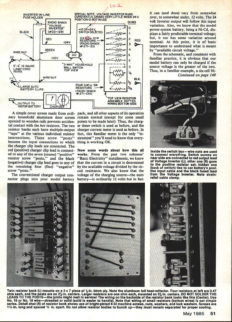
The system allows easy charging of Ni-Cd motor packs up to 14 cells without splitting series-connected packs. The unit is powered from a car battery (connect directly to the battery posts). The inverter doubles the car's nominal 12 V input to about 24 V and can deliver up to approximately 3 A. A single-pole double-throw switch selects either the 12 V source (direct from the car battery) or the 24 V inverter output, and the selected positive lead is routed through the coarse resistor bank. A separate resistor set in the negative lead provides fine adjustments. The charger plugs into the output of this resistor network; the charger’s timer and ammeter are used as usual.
SPECIAL NOTE: The voltage inverter runs constantly and draws very little current when the 24 V position is not in use.
Construction details
- Mount everything on the plywood base. Attach the charger (use double-sided Velcro for easy removal) and position the inverter, switch, and fuse holder.
- Assemble the coarse resistor bank as a series string of six 1-ohm, 10-watt resistors. Provide screw-post taps at each resistor junction so you can select multiple total resistances (coarse steps).
- Assemble the fine resistor bank in the negative lead with a few resistors and multiple taps for small changes; mount on screw posts as well.
- Use machine-screw posts (No. 6/8/10) as mechanical/electrical terminals—do not solder the resistor leads to these posts because the resistors will get hot and solder may melt.
- Attach an aluminum-foil reflector (double-stick tape) beneath the resistors on the birch plywood plate to prevent burning the wooden mount.
- Cover the resistor area with an aluminum window-screen cage epoxied to wooden rails to prevent accidental contact. Leave enough clearance above the resistors for heat.
- Use doubled No. 16 lamp cord for the battery input leads; color-code the wires and connect to the correct car-battery posts.
How it works (basic electricity applied)
Charging current is determined by the available circuit voltage (ACV) divided by the circuit resistance (Ohm's Law: R = V / I).
Example (six-cell pack):
- Under charge a Ni-Cd cell may "float up" to ~1.5 V per cell. A six-cell pack can reach about 9 V.
- With a 12 V source, ACV = 12 − 9 = 3 V.
- If the pack is 800 mAh and you want ~3 A charge: R = V / I = 3 V / 3 A = 1 ohm total resistance in the charging circuit.
- Use the resistor taps to provide approximately 1 ohm between the charger positive and negative connections.
Procedure in practice:
- Set the source voltage (12 V or 24 V) with the switch.
- Start with the highest-resistance taps (lowest current) on both coarse and fine banks.
- Turn on the charger timer and note the charger's ammeter.
- Move the positive and/or negative clip to lower resistance taps until you achieve the desired charge current (do not exceed ~3 A).
Charging current will naturally fall as the pack charges because the pack terminal voltage rises, reducing ACV across the resistor. It is usually sufficient to start a little above the desired average current since the current will taper.
Charging seven-cell (and larger) packs
Seven-cell packs are often troublesome on a 12 V source because:
- A charged seven-cell pack can reach ~10.5 V, leaving only ~1.5 V ACV with a 12 V source. That requires very low circuit resistance and is sensitive to contact resistance and connection quality.
- At the start of charge the pack may be ~8.4 V (1.2 V per cell), giving ACV ~3.6 V. The ACV can vary roughly 2:1 during charge, so charge current varies widely for a fixed resistance.
Solution:
- Use the 24 V inverter position and select enough resistance to set the desired current. For a seven-cell pack:
- ACV ≈ 24 − 10.5 = 13.5 V (late in charge)
- ACV ≈ 24 − 8.4 = 15.6 V (early in charge)
- Because ACV is much larger, you can use higher resistance (several ohms), making the charging current more stable and forgiving of contact resistance variations. In short, use 12 V for six or fewer cells; use 24 V for seven or more.
Limitations and practical considerations
- Heat and efficiency: All charging techniques waste power as heat in the control resistors. The greater the ACV across the resistor, the more power is wasted. This is generally only an annoyance (like a hot light bulb), but avoid unnecessary high-voltage use when a lower voltage will suffice.
- Current limit: The inverter and chosen resistors effectively limit the system to about 3 A. The 10-watt resistor rating constrains current: for a 1-ohm resistor, Imax = sqrt(P / R) = sqrt(10 / 1) ≈ 3.16 A. Choosing resistors and inverter within this limit is important.
- Charging time: A 3 A charge into 800 mAh cells is convenient (3 A × 15 min ≈ 750 mAh). For 1.2 Ah cells, 3 A for ~20–24 minutes is needed to reach label capacity; use timer intervals accordingly.
- Charger internal circuits: Some chargers include trickle circuits (small lamp or resistor across timer contacts) or internal fixed resistors/switches. These may not tolerate 24 V input. You may wish to disconnect trickle components or jumper-out internal resistors if they interfere with your external resistor network. Check the charger's manual or with the manufacturer if unsure.
- Charger compatibility: Most Astro or Leisure chargers capable of handling two 12 V batteries in series (24 V input) will work. Verify the maximum allowable input of your specific charger model before using the 24 V source.
Final notes and future work
This system is a highly versatile, heavy-duty charging setup built from readily available parts. Everything mounts on a 9 x 13 in. base and is easily disassembled (charger held with Velcro). It provides a convenient way to charge Ni-Cd flight packs up to 14 cells.
I'll present a "deluxe" version later that uses two modified voltage inverters plus an efficient, smoothly adjustable solid-state switching-mode current regulator to charge up to 30 V at beyond 4 A.
Please forward any questions with SASE to: Bob Kopski 25 West End Dr. Lansdale, PA 19446
Happy electric landings!
Transcribed from original scans by AI. Minor OCR errors may remain.

