

Radio Control: Electrics
Bob Kopski, 25 West End Dr., Lansdale, PA 19446
The gold came home from Holland with the United States F3E team in August! This is an historic first for the U.S., since several attempts in previous years ended in disappointment. But this year it was our turn; the U.S. is now the one to beat in the future.
The team victory was made possible by the individual high scoring of the team members. Jerry Bridgeman was second overall, Jason Perrin was third, and Steve Neu was seventh. Austria and Germany came in second and third, respectively. In all, 39 pilots represented 13 countries.
And since it’s an obvious question, be advised that the U.S. fliers used highly modified and customized Astro Cobalt 60s to do the job—another first as well. The dominant motors this year were:
- Astro
- Keller
- Platenburg
For more information on the nature of the F3E activity, please refer to this column in the May and June ’92 issues of Model Aviation. Congratulations, Jerry, Jason, and Steve!
The Electric Connection Service
The Electric Connection Service has two modelers to list this month.
- Steve Gurley, 1104 E. Campus Dr., Tempe, AZ 85282.
Steve wrote to tell me about the first Arizona Model Aviators’ Electric Fun-Fly, held on July 11. This event took place on the Spook Hill flying field near Phoenix—the site of the ’90 Top Gun Invitational. Steve was very pleased with the results of this first-ever meet and went on to enthusiastically describe some of the activity in detail—such as the helicopter flying. He is also interested in attracting more area folks who are electrically oriented. Please do get in touch with Steve, and join the local electric fun. Don’t forget to tell ’im “Bob sent ya”!
- Charles and Carl Varvaro (father and son), 420 E. Newmark Ave., Monterey Park, CA 91754; Tel.: (818) 307-9070.
These modelers have had a great time flying a wide variety of electrics in recent years, but they do so pretty much alone. They are anxious to attract others in the immediate area to join in the electriflying fun. Now it’s your move—look ’em up, gang. Then start working on a club name—okay?
Best wishes to Steve, Charles, and Carl with their individual electric pursuits and their thrust to attract more interested modelers. Don’t forget to let me know how it all goes, guys.
Photo captions and corrections
Just as I suspected—the October ’92 column photo captions got the “art” treatment just like I discussed last month for the September ones! I’ve since hammered on the Editorial and Production folks at the magazine to get them to change their ways and keep the technical information in the captions—just like I write ’em.
In the two photos on the top of page 64 in the October ’92 issue, the plane is a 1/5-scale Mustang based on the Pica kit. The 20-lb. model features retracts, retract doors, and flaps. The Citabria in the lower left corner of the same page is powered by a direct-drive sport-wind version of the Astro 60. The 32 1,500-mAh cells are controlled by a Jomar SC6. Prop is an APC 16 x 12. All-up weight is 12 lb. with an 18-oz. wing loading. A typical flight is over eight minutes with mild aerobatics.
In the lower right-hand photo, the Electron uses a pattern-wind 60 to turn a 12 x 12 from energy stored in 28 1,200-mAh Ni-Cd cells. Dave Brown used mechanical retracts and retracted the 6.5-lb. Pucara on page 65. It used 11 x 9 props and did four-minute flights.
All this information was contained in my original written captions but did not wind up in that issue. I have many letters specifically interested in such details, and I'm very much less than happy with having to repeat this information.
I'm really upset about this situation for two reasons: the information is getting to you very late, and I'm forced to take up space repeating it that would be better used for other purposes. Well, at least they promised me that it won't happen again.
Readers and computers
Readers were quick to react to my comments in recent issues regarding computers in modeling. In particular, reaction to my feeling regarding DOS-based PCs was strong and took two forms. One side was the "attaboy" side—those readers who clearly agreed with me that these systems are terrible to use. The other side—i.e., those readers who are pro-PC—turned out to be both understanding and helpful. I actually got several letters from readers who offered assistance to me in my struggle with this miserable system.
Now, to be honest, I fully expected a barrage of pro-PC reaction, since after all many folks routinely use this stuff, and I was (purposely) strong in expressing my feelings toward it. But I was both surprised and very happily impressed with the offers of help and the general absence of defensiveness. I've said it before, and it holds true— you folks are the greatest! Thank you all for taking the time to react in whatever way you did.
Measuring motor current
One of the most difficult tasks an electric modeler may face is trying to measure motor current. Ordinarily, the task of measuring current is very easy: nearly all readily available multimeters come equipped to do so. In principle and practice, all one needs to do to measure current is connect a current meter in series with any current-carrying circuit. So why is this task more difficult for motor current?
What makes motor current measurement less than simple is that our power systems operate with relatively high currents—well past the ranges found on most common multimeters. Most ordinary meters have current ranges up to 10 amps or less, and this doesn't handle the typical "20-something" amps we're used to running through our power systems. Therefore, some approach other than the simple application of a multimeter set on a current scale is needed.
If you can access these references, you'll be well ahead: beginning around March '85 this column presented a miniseries on basic electricity. The December '85 issue discussed voltmeters and current meters and described how they worked. The April '86 issue presented extensive detail on how to make a high-current shunt—a device to allow you to easily measure motor current for most any system you're likely to use.
For everyone, here's an updated look at how to easily meet this measurement challenge.
#### What is a shunt?
A shunt is another word for a specialized resistor—in particular, a low-resistance, precision resistor. This resistor is deliberately inserted in series with the circuit so that circuit current must flow through it. At the same time, this resistor is of such low resistance that its presence does not noticeably affect the operation of the circuit.
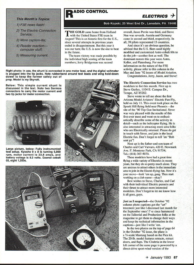
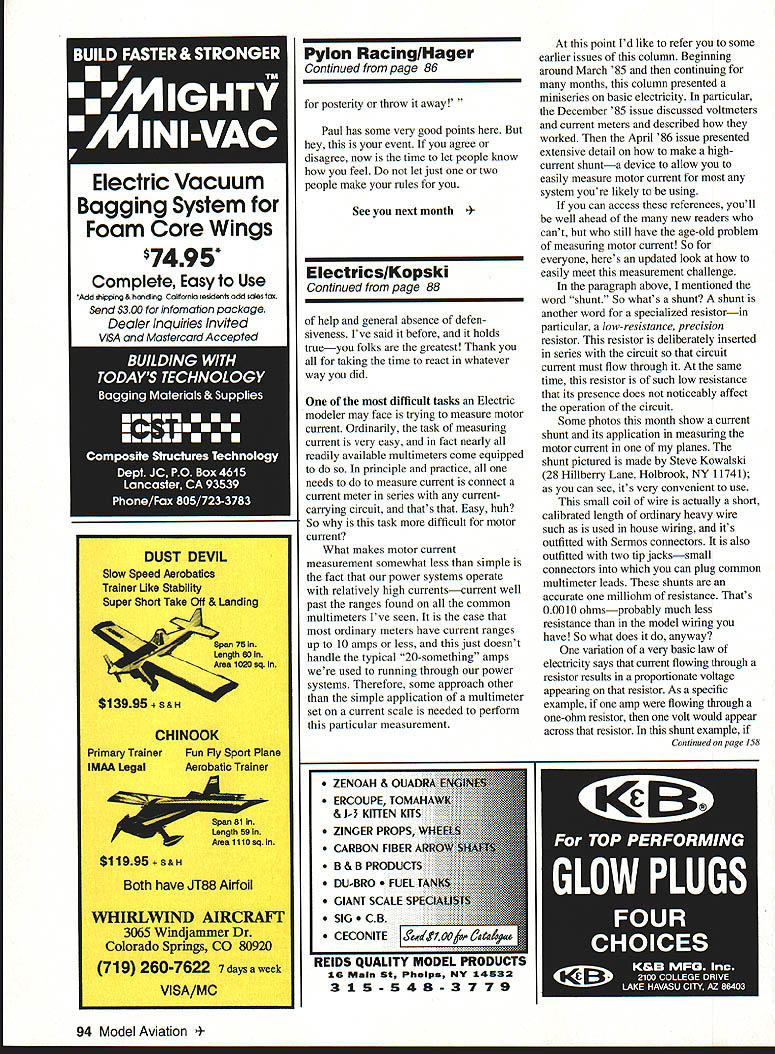
The shunt pictured was made by Steve Kowalski (28 Hillberry Lane, Holbrook, NY 11741); as you can see, it's very convenient to use. This small coil of wire is actually a shunt—a calibrated length of ordinary heavy wire such as used in house wiring, and it's outfitted with Sermos connectors. It is also outfitted with two tip jacks—small connectors into which you can plug common multimeter leads. These shunts are an accurate one milliohm of resistance. That's 0.0010 ohms—probably much less resistance than in the model wiring you have!
One variation of a very basic law of electricity says that current flowing through a resistor results in a proportionate voltage appearing across that resistor. As a specific example, if one amp were flowing through a one-ohm resistor, then one volt would appear across that resistor. In this shunt example, if one amp were flowing, then one millivolt would appear across it. Thus, Steve's shunt is a one-millivolt-per-amp shunt.
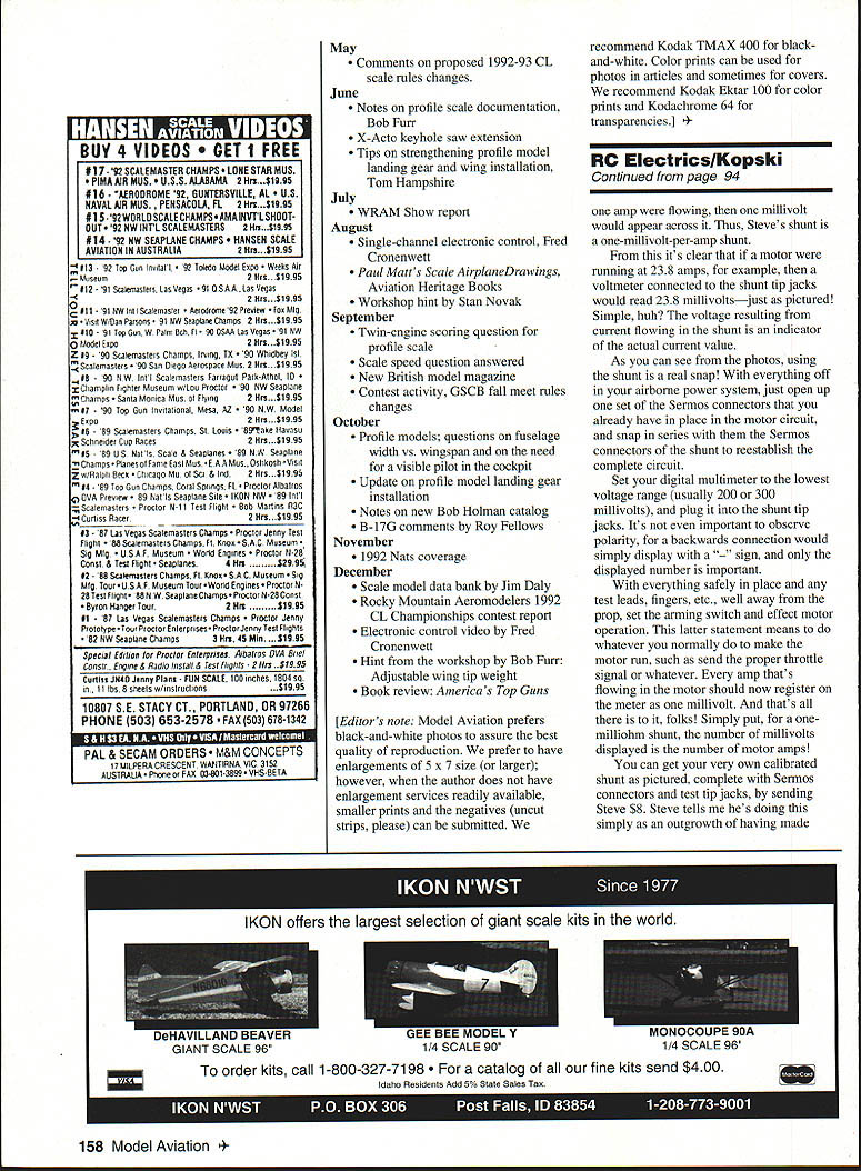
From this it's clear that if a motor were drawing 23.8 amps, for example, then the voltmeter connected to the shunt tip jacks would read 23.8 millivolts. The voltage resulting from current flowing in the shunt is an indicator of the actual current value.
#### How to use the shunt
As you can see from the photos, using the shunt is straightforward. With everything off in your airborne power system, open up one set of the Sermos connectors that you already have in the motor circuit, and snap in series with them the Sermos connectors of the shunt. Be sure that the meter is connected to the shunt with the meter turned off. Set your digital multimeter to the lowest voltage range (usually 200 or 300 millivolts), and plug in the two shunt tip jacks. It's not important to observe polarity; a backwards connection would simply display a "-" sign, and only the displayed number is important.
With everything safely in place and any test leads, fingers, etc., well away from the prop, set the motor running and check the meter. The shunt allows you to see motor current in the same way that an ammeter does, without having to use a bulky in-line meter. The battery voltage will also show some drop as the current increases.
You can get your very own calibrated shunt as pictured, complete with Sermos connectors and test tip jacks, by sending Steve $8. Steve tells me he's doing this simply as an outgrowth of having made them for his own use.
#### Considerations and accuracy
There are, however, a few considerations to keep in mind when using a low-output copper shunt.
- Temperature stability: Copper is not temperature-stable; its resistance increases by about 4% per 10°C. This means you can get erroneously high readings at elevated temperatures, and lower readings under cold conditions. On the other hand, if you now have no effective way to measure motor current, this is not a catastrophic problem. I have two of these shunts myself and find they are usually more convenient to use than my own temperature-stable one described in the April '86 MA reference.
- Meter accuracy: Typical economy multimeters attempting to display only one millivolt out of a 200-millivolt range could actually have an error of several millivolts. To test this, I evaluated three economy Radio Shack meters of different types as well as a much better quality lab meter and found excellent agreement among them.
One simple test you can perform to add credibility to such measurements is to get two voltage readings—one for each meter lead polarity. That is, read the shunt voltage with the meter leads connected to the tip jacks both ways (normal and reverse), and compare the results. This technique will show up any meter offset near zero, and you can simply average the two resulting readings if they differ. A meter with no significant zero offset should produce the same magnitude (number), whether it shows a "+" sign or not.
- Autoranging meter issues: I found that some autoranging meters had trouble with this motor current measurement because motor noise seemed to confuse the meter and it constantly tried to find the right range. This could likely be corrected by installing a large capacitor across the meter leads near the meter (not near the shunt)—several tens to hundreds of microfarads should do it. Otherwise, I suggest using meters with a manually set range.
Finally, for most applications, comparative measurements are more important than absolute accuracy. For example, if you're interested in the current drain associated with different props, a nominal but consistent error will affect both readings similarly. Any difference in the two readings is still a very good indicator of prop effects.
So, if you've been struggling with motor current measurements, do consider Steve's shunt as an economical approach to this tricky problem. I'm sure you'll be pleased. Thanks, Steve, for showing me your great idea at the June '92 LVRCS meet!
So concludes the first column of the new year. Please enclose an SASE with any correspondence for which you'd like a reply. And just think—only a few more issue months, and it will be spring again!
Happy Electric Landings
Transcribed from original scans by AI. Minor OCR errors may remain.

