
RADIO CONTROL ELECTRICS
Bob Kopski, 25 West End Dr., Lansdale, PA 19446
This Month's Topics
- The Electric Connection Service;
- New items—Flightec and Hobby Lobby;
- More computer/Electric stuff;
- Seven-cell charging—for beginners;
- Charge radios free!—for experts.
ECS Presents
Rich Flinchbaugh, 28 Harrison Ave., Newport, RI 02840, is interested in both electric planes and boats and so far has several powered by seven‑cell systems. He would like to meet up with others in his area who share electric interests. Why not get in touch with Rich and make some more quiet power happen—collectively!
New items
This month brings two new items to our attention.
First, a new product from Flightec—the speed control company. This time, however, it's not electronic; it's electric! Phil Thayer—the boss—tells me he's got a new plane to market. It's a 395‑square‑inch delta called the Vee‑olt 05a—a really neat‑looking ship that weighs about 32 ounces. It's made of virgin foam material, and Phil says this RTF (ready‑to‑fly) can be ready in three hours. Price of the kit is $28 plus $3 shipping and handling direct. I expect to get a Vee‑olt going soon myself. You can get yours from Flightec, 21 Juniper Way, Hamilton, NJ 08619.
Next, Hobby Lobby's newest catalog—#21—has arrived. These catalogs are truly amazing—many top‑notch color pictures of a broad base of modeling products, including lots of motors, planes, and accessories for electric. This is recommended reading. You can get yours free (in the U.S.) by writing Hobby Lobby, 5614 Franklin Pike Circle, Brentwood, TN 37027; Tel.: (615) 373‑1444.
More computer/Electric stuff
In the December 1992 column I mentioned an E‑modeling computer program developed by reader Ken Rusnok. The program runs on PC/DOS machines and is designed to evaluate the performance of motor/propeller combinations. Ken has checked the program with reader input of performance info and is now satisfied with it. You can obtain a copy free by sending a 3½‑ or 5¼‑inch disk (virus free, please!) and a prepaid disk mailer SASE to Ken Rusnok, P.O. Box 4643, Fayetteville, AR 72702. I have it installed on my machine and recommend it.
As always, I lament that much of this neat computing stuff is written for PC/DOS—the concrete sailplane of computer systems.
Seven‑cell charging — for beginners
Beginners keep arriving, and that's good. Periodically I like to share basics that more experienced E‑modelers usually already know. This month I address a situation that often frustrates even experienced modelers: charging seven‑cell packs from a car battery.
Six‑cell and seven‑cell power systems are very popular. Many electric kits use these packs: Electra, Mirage, PT Electric, Challenger, AeroLectric, Eclipse, and more. These planes are normally used with C‑five motors, which run on six‑ to seven‑cell packs.
These systems combine reasonable economy with practicality: they allow a model size and power range that's easy to build, can carry radio equipment, and are relatively rugged. Many six‑ and seven‑cell packs and chargers are on the market, driven by the competitive model car market.
However, charging seven‑cell packs with economy chargers can be frustrating. Modelers often have difficulty maintaining a desired charge current over the charging period—the current keeps dropping. Sometimes the charger is blamed, but usually that's not fair. Here's why.
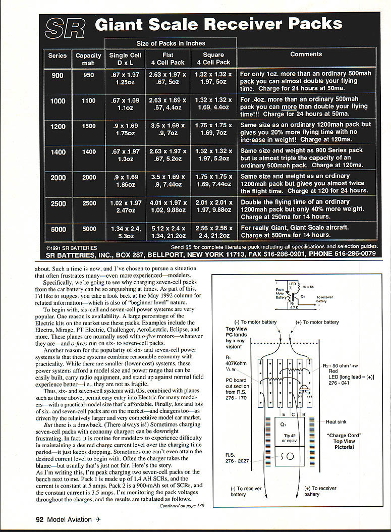
I am peak charging two seven‑cell packs on the bench. Pack 1 is made up of 1.4 Ah SCRs, and the current is constant at 5 amps. Pack 2 is a 900 mAh set of SCRs, and the current is constant at 3.5 amps. I monitored the pack voltages throughout the charges; the results are tabulated below.
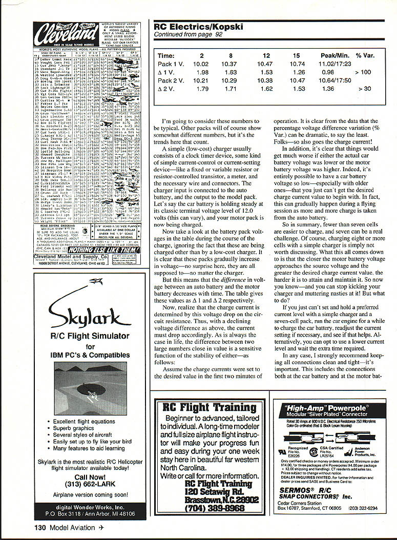
Time (min): 2 8 12 15 Peak/Min. % Var. Pack 1 V: 10.02 10.37 10.47 10.74 11.02/17.23 >30 Δ1 V: 1.98 1.63 1.53 1.26 0.98 >100 Pack 2 V: 10.21 10.29 10.38 10.47 10.64/17.50 >30 Δ2 V: 1.79 1.71 1.62 1.53 1.36 >30
These numbers are typical in trend if not in exact values. A simple (low‑cost) charger usually consists of a clock timer, a simple current‑control or current‑setting device (fixed or variable resistor, or resistor‑controlled transistor), a meter, and the necessary wires and connectors. The charger input is connected to the car battery, the output to the model pack. Assume the car battery is holding steady at about 12.0 volts (it can vary) and your motor pack is being charged.
The pack voltages above gradually increase during charge, as expected. That means the difference in voltage between the car battery and the motor battery decreases with time (Δ1 and Δ2 in the table). The charge current is determined by that voltage difference across the circuit resistance; therefore, as the voltage difference declines, the current drops.
Because the difference between two similar large voltages is a sensitive function of either voltage's stability, the percentage variation in the voltage difference—and thus in the charge current—can be dramatic. If the car battery voltage is lower or the motor battery voltage is higher, things get worse. An older car battery may be so low that you can't get the desired charge current to begin with; it can also drop during a flying session as you draw more charge from the auto battery.
In summary: fewer than seven cells are easier to charge; seven can be a real challenge; eight or more cells with a simple charger is usually not worth discussing. The closer the motor battery voltage gets to the source voltage and the higher the desired charge current, the harder it is to attain and maintain it. So don't immediately blame the charger.
What to do?
- Run the car engine for a while to raise the car battery voltage; readjust current setting if necessary.
- Use a lower current level and accept a longer charge time.
- Keep all connections clean and tight at both the car battery and the motor battery.
- Forget charging from the cigarette lighter—that's usually impractical.
- A more sophisticated charger (constant‑current electronics, voltage‑boost circuitry) is the best solution, though not simple or inexpensive.
Plenty of modelers manage lots of great flying with seven cells and simple chargers, so it can be done.
Charge radios free! — for experts
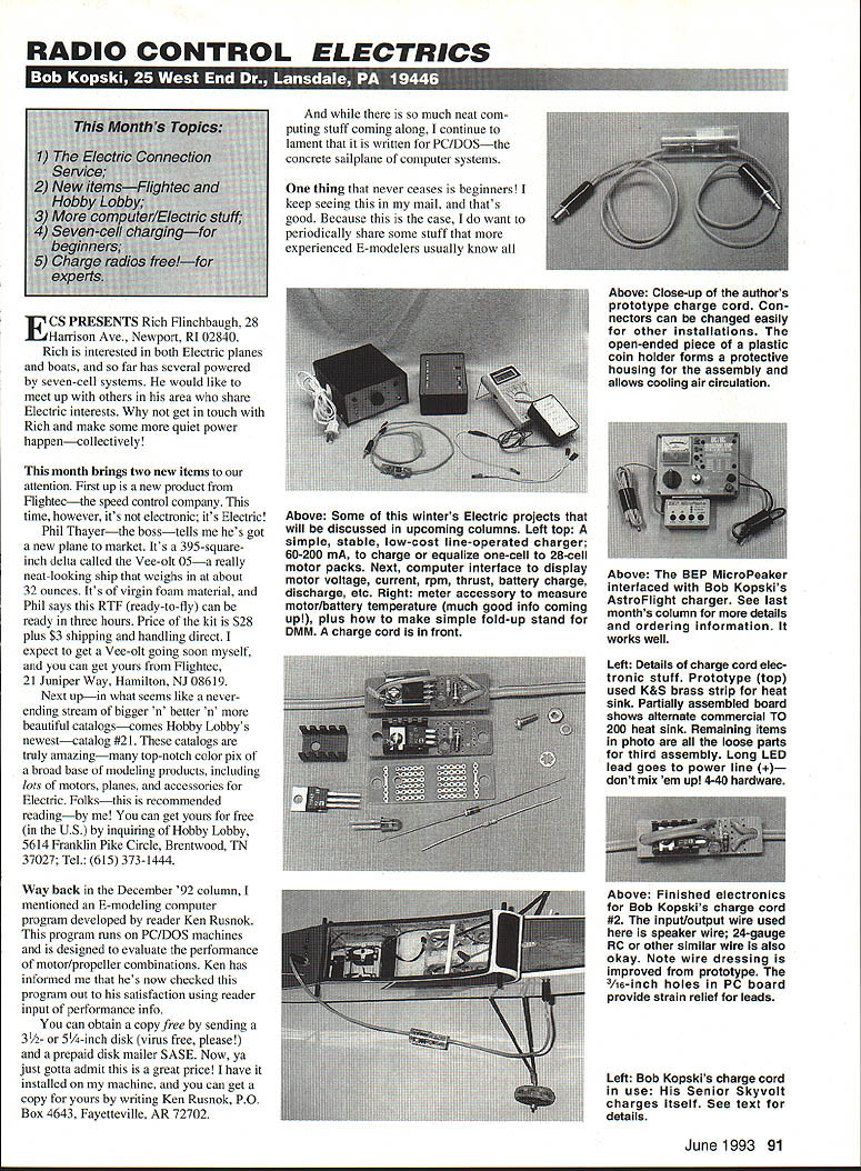
Charging receiver (radio) batteries can also be a nuisance, especially if you have several planes. I often have several electrics stacked and ready, so I developed a simple "self‑charge" charge cord to top off receiver packs using leftover motor battery charge.
Normally, when I land an electric, some charge remains in the motor battery—enough to be useful for topping off a receiver pack. Most of my planes are seven cells and up; my receiver packs are usually four cells at 250 mAh. I rarely fully discharge receiver packs, so it takes little to top them off.
A charge cord is a simple electronic assembly that delivers about 21–23 mA into a receiver pack from onboard motor batteries ranging from seven to 24 cells or more. All that's needed is some charge left in the motor pack or a few minutes of motor battery charge before putting the plane away.
I have three such cords and use them to charge a radio pack inside the plane or transfer charge from one plane to another. A full overnight charge is rarely needed; 22–24 mA will top a 250 mAh pack from half empty in about six hours (roughly 132 mAh delivered). If your motor battery cells are 1.4 Ah, they'd only need about one‑tenth of their capacity to do the job.
My planes use the coaxial power plug/jack popularized by Astro for motor battery charge plugs. My receiver packs are charged via a standard 1/8‑inch phone jack. The charge cords have the appropriate connectors—motor pack input and receiver pack output.
How it works
- The charge cord is a simple current regulator that maintains a nearly constant output current regardless of the motor battery cell count within the specified range.
- Resistor R1 and a red LED are connected across the source leads. LED brightness varies with cell count, but the LED voltage remains about 1.8–2.0 V, so it acts as a voltage reference.
- Transistor Q1's base is connected to the R1–LED junction; the emitter follows that junction about 0.7 V lower. The emitter resistor (R2) is forced to pass the set current, resulting in about 21–23 mA into the receiver pack.
- For R2 ≈ 56 ohms, approximately 22 mA flows in the emitter and thus in Q1's collector, which goes to the radio battery. The current is quite temperature‑stable because LED and base‑emitter temperature responses cancel.
- If no radio battery is plugged in, the LED goes out (some small drain still occurs), and if the source battery runs down below the useful range, the output current drops accordingly.
Parts and construction
- Except for your specific connectors and R2, most electronic parts can be obtained from Radio Shack (RS) stock; RS can special‑order the needed 56‑ohm resistor.
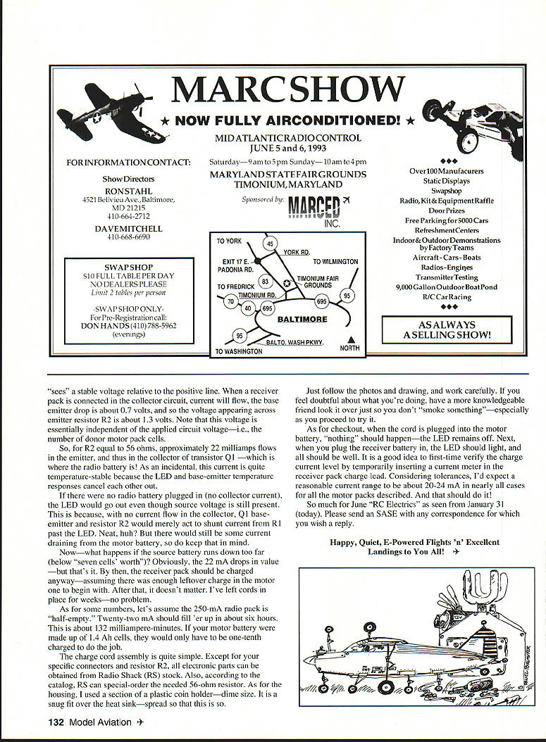
- I used a small plastic coin holder (dime size) as the housing and a small heat sink. Follow photos and drawings and work carefully.
- If in doubt, have a knowledgeable friend review the assembly to avoid damaging parts.
Checkout
- When the cord is plugged into the motor battery alone, the LED should remain off.
- When you plug the receiver battery in, the LED should light.
- Verify the charge current with a meter in the receiver pack charge lead; expect about 20–24 mA.
That should do it.
So much for June "RC Electrics" as seen from January 31 (today). Please send an SASE with any correspondence for which you wish a reply.
Happy, quiet, E‑powered flights ’n’ excellent landings to you all!
Transcribed from original scans by AI. Minor OCR errors may remain.

