
RADIO CONTROL ELECTRICS
Bob Kopski, 25 West End Drive, Lansdale, PA 19446
This Month's Topics:
- The Electric Connection Service
- The Charge Cord — Followup
- SCRC Performance — Followup
- Revolt Telemetry
- Flightec Data/Computer Interface
- Beginner Info
The Electric Connection Service
THE ELECTRIC Connection Service brings in a modeler from the First in Flight state. Don Miner, 232 Dundee Circle, Hendersonville, NC 28792, tells me that there are very few electric fliers and not even one formal club (including the wet kind) in his area.
There also aren't many fields, so I'm appealing on Don's behalf for all interested in that area to connect with him — especially if you have a field to share in your back pocket. Perhaps you folks can combine knowledge and resources and develop an E-club for all to enjoy. And do let me know how it goes.
The Charge Cord — Followup
The Charge Cord as presented in the June and October columns has brought in its share of reader response. Some of this was due to errors that crept in along the way (sorry!), which several readers caught. Since I know the device basically works very well, if anyone is having continuing difficulty due to the column "glitches" that occurred, you're welcome to send your Charge Cord to me and I'll do my best to fix it — free!
Here are a few reader questions and answers that may be of interest to others:
- One modeler thought something was wrong because while the Charge Cord seemed to be working, the heat sink wasn't getting warm or hot. The Charge Cord is designed to work from motor batteries ranging from 7 to 24 cells. It develops a receiver battery charge current of a nearly constant 20 mA or so, no matter what motor battery is used. The Charge Cord electronics operate on the voltage difference between the motor and receiver battery, and this can range from about 3 to 30 volts, depending on how many cells are in the motor battery.
The low end of this range will not cause any significant power dissipation and heating, but the upper end will; you will feel some temperature rise in the heat sink when larger motor batteries are used. This is normal, and that's why the heat sink is there — so you can use most any motor battery.
- The current that charges the receiver does not flow through the LED. Rather, it is regulated through the transistor. Incidental to this you may notice some LED brightness variation depending on motor-pack cell count. This, too, is perfectly normal.
- You can (and should) test the output current of a newly completed Charge Cord to verify that all is working properly. I suggest you first use a seven-cell motor battery for the source, and a current meter in series with a 180-ohm resistor (1/4 watt or larger) as the load. This meter/resistor combo is a temporary substitute for your receiver battery. The resistor will limit the output current to prevent meter damage should anything be wrong with your new cord assembly.
If all is well, the meter should indicate a current level of about 20 to 24 mA. The LED should glow when the meter/resistor is present, and not glow when no load is present. If this all works OK, substitute a larger motor (source) battery and verify that the meter reading remains unchanged. If all is well, remove the meter/resistor load and use the Charge Cord for its intended purpose: charging receiver batteries, as described in the June column.
SCRC Performance — Followup
The August column included computerized printouts of the charge/discharge performance of some 1.4 Ah SCRC cells and some 1.7 Ah SCRC cells. That data clearly demonstrated that the latter performed badly (relatively speaking) — no better than the 1.4 Ah cells. This SCRC performance shortfall was the sort of thing I'd been hearing about, and I had the same disappointing experience.
That column also noted that, as it was being written, columnists John Mountjoy and Charlie Spear of RC Report had been reporting very good results with their SCRCs. Following the appearance of my August column, friend John graciously sent me one of his packs to try out. He was right: the pack performed very well, producing at least the rated 1.7 Ah when tested in the exact same setup I previously used.
John obtained his SCRCs from PTI at $6.80 per cell. It seems that PTI sorts through their cells and keeps only the best.
Revolt Telemetry
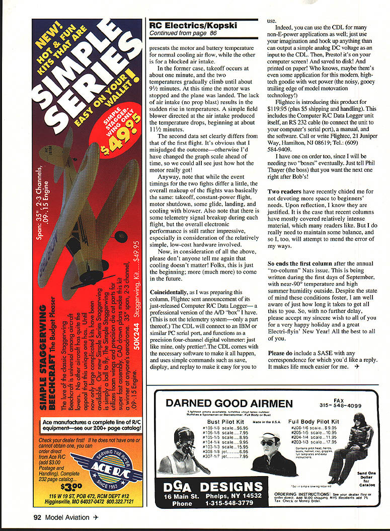
The airborne portion of the Revolt telemetry system consists of a simple holeboard assembly of the electronics in the plane. This board contains a low-power RF transmitter on 26.995 MHz, taken from a Radio Shack toy car. AM modulation encoding is accomplished with a Signetics 5044 — the chip used in some ordinary RC transmitters to encode servo-position information. I'm using two of its available seven channels.
The board also contains some op-amp signal conditioning circuitry to interface sensors to the 5044. Power comes from the Revolt's motor battery; this one has a 25-volt pack of 14 cells. For starters I chose to sense and send both motor and battery temperature during flight. This was easy to do, allowed me to get everything working, and yielded some interesting results. I simply CA'ed (cyanoacrylate-glued) an LM34DZ temperature sensor to both the Astro 25 housing and a motor battery cell in a mid-pack location. Anything I can sense I can also use as input to the encoder, and in the future I'm after things like motor current, voltage, RPM, airspeed, etc.
The ground end of this data link begins with a Hitec two-channel car receiver. What would normally be the two servo outputs go to some pulse-width-to-voltage conversion circuitry. This converts the full-range pulse-width motion of 1 to 2 milliseconds into a DC voltage range of 0 to 1.0 volts. This in turn is input to my A/D converter box (the same item I used to get the battery charge/discharge data).
Finally, the "box" is connected to the notebook computer serial port, and this results in a live display of motor and battery degrees Fahrenheit — in flight! The estimated overall system peak error is about two degrees.
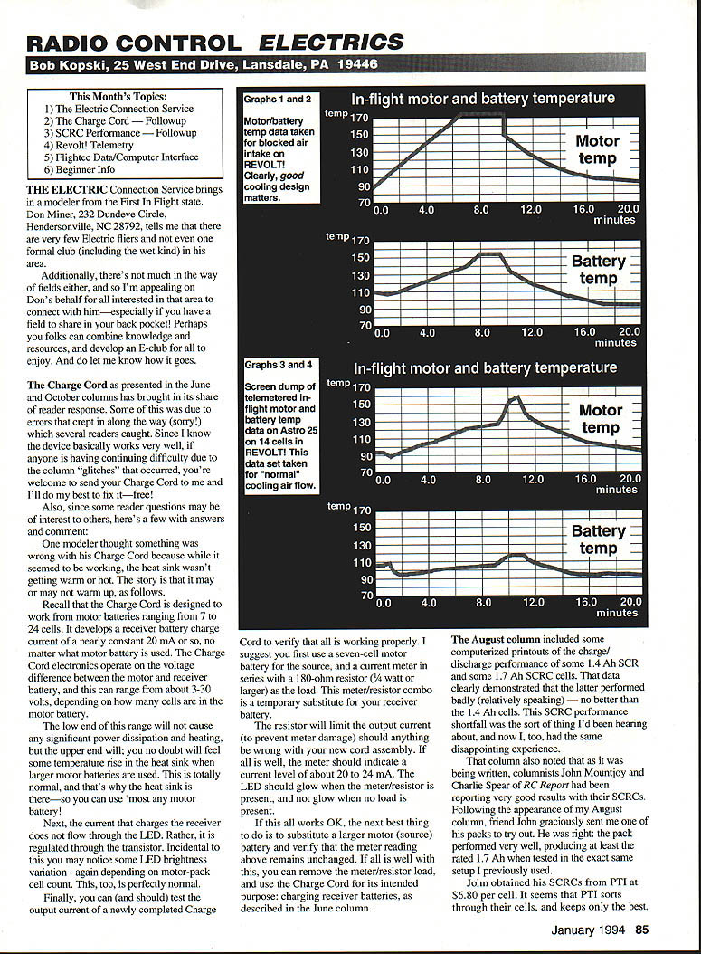
Referring to the graphs: both data sets (flights) were made with the same constant throttle setting. This less-than-full-power condition resulted in about equal flight duration, with the plane being flown in a large oval pattern each time. One graph pair presents the motor and battery temperature for normal cooling airflow, while the other is for a blocked air intake.
In the normal-cooling case, takeoff occurs at about one minute, and the two temperatures gradually climb until about 9½ minutes. At that time the motor was stopped and the plane was landed. The lack of prop blast (no air intake) results in the sudden rise in temperatures. A simple field blower directed at the air intake produced the temperature drops, beginning at about 11½ minutes.
The second data set clearly differs from the first flight. It's obvious that I misjudged the outcome — otherwise I'd have changed the graph scale ahead of time so we could all see just how hot the motor really got!
Note that while the event timings for the two flights differ a little, the overall makeup of the flights was basically the same: takeoff, constant-power flight, motor shutdown, some glide, landing, and cooling with blower. Also note that there is some telemetry signal breakup during each flight, but the overall electronics performance is still rather impressive, especially considering the relatively simple, low-cost hardware involved.
Please don't anyone tell me again that cooling doesn't matter! This is just the beginning; much more to come in the future.
Flightec Data/Computer Interface
Coincidentally, as I was preparing this column, Flightec sent an announcement of its just-released Computer R/C Data Logger — a professional version of the A/D "box" I have. (This is not the telemetry system — only a part thereof.) The CDL will connect to an IBM or similar PC serial port, and functions as a precision four-channel digital voltmeter: just like mine, only prettier. The CDL comes with the necessary software and uses simple commands such as save, display, and replay to make it easy to use.
You can use the CDL for many non-E-power applications as well; hook up anything that can output a simple analog DC voltage as an input to the CDL and it will display, save, and print the data.
Flightec is introducing this product for $119.95 (plus $5 shipping and handling). This includes the Computer R/C Data Logger unit itself, an RS-232 cable (to connect the unit to your computer's serial port), a manual, and the software. Call or write Flightec, 21 Juniper Way, Hamilton, NJ 08619; Tel: (609) 584-9409.
I have one on order too, since I will be needing two "boxes" eventually. Just tell Phil Thayer (the boss) that you want the next one right after Bob's.
Beginner Info
Two readers have recently chided me for not devoting more space to beginners' needs. Upon reflection, I know they are justified. Recent columns have mostly covered relatively intense material, which many readers like. But I do need to maintain some balance, and I will attempt to mend the error of my ways.
So ends the first column after the annual "no-column" Nats issue. This is being written during the first days of September, with near-90° temperature and high summer humidity outside. Despite the state of mind these conditions foster, I am well aware of just how long it takes to get all this to you. With no further delay, please accept my sincere wish to all of you for a very happy holiday and a great Electri-flyin' New Year! All the best to all of you.
Please include a SASE with any correspondence for which you'd like a reply. It makes life much easier for me.
Transcribed from original scans by AI. Minor OCR errors may remain.

