
Radio Control: Giant Scale
John A. de Vries 4610 Moffat Lane Colorado Springs, CO 80915
Overview
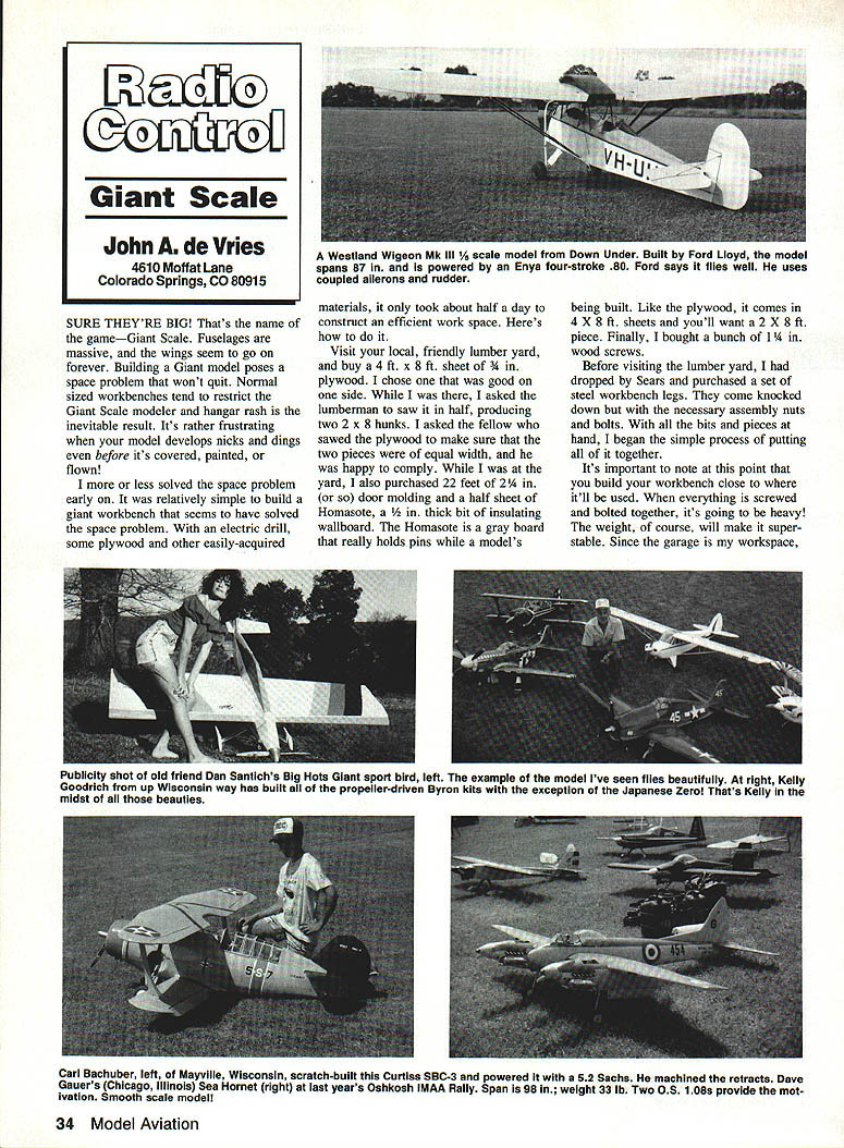
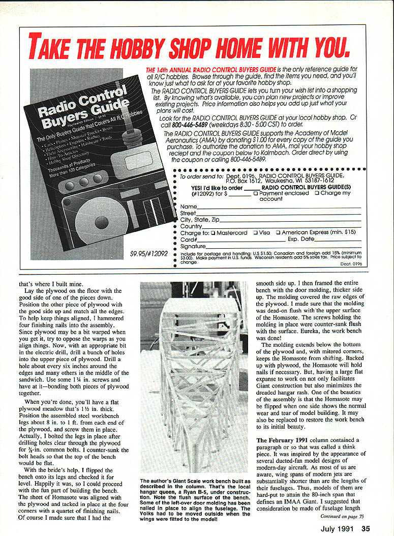
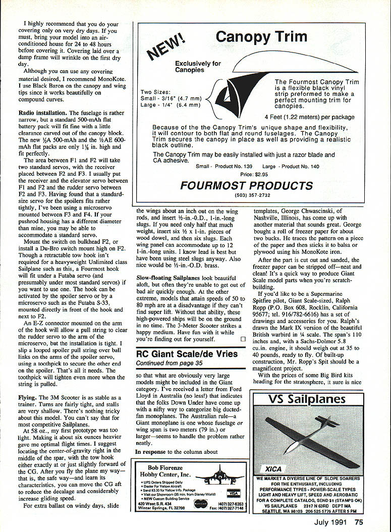
Sure they're big — that's the name of the game. Giant Scale fuselages and massive wings seem to go on forever. Building a Giant model poses a persistent space problem: normal-sized workbenches restrict the Giant Scale modeler and hangar rash is often the inevitable result. To solve this I built a simple giant workbench that took about half a day and gave me an efficient workspace. Here's how.
Workbench Construction
Materials
- 1 sheet 4 ft. x 8 ft. of 3/4-in. plywood (choose one good side)
- Lumberman sawing to produce two 2 ft. x 8 ft. pieces (equal width)
- About 22 ft. of door molding (about 2¼ in. wide)
- 1/2-in. Homasote (insulating wallboard), 2 ft. x 8 ft. piece
- 1-1/4-in. wood screws (plenty)
- 3/8-in. common bolts (for leg attachment)
- Set of steel workbench legs (knock-down style from a hardware store)
- Finishing nails (few)
- Tools: electric drill with appropriate bits, hammer, saw (if needed), countersink
Assembly (step-by-step)
- Choose the bench location and build it close to where it will be used — the finished bench will be heavy and super-stable.
- Lay one plywood piece with the good side down. Position the other piece with the good side up so the edges match and warps oppose each other.
- Hammer four finishing nails to hold the sandwich while assembling.
- Drill holes through the upper piece of plywood about every 6 in. around the edges and several in the middle.
- Fasten the two plywood pieces together with 1-1/4-in. wood screws. When finished you will have a flat panel about 1-1/2 in. thick.
- Position the assembled steel workbench legs about 8 to 12 in. from each end and mark bolt locations.
- Drill holes clear through the plywood and bolt the legs with 3/8-in. common bolts. Countersink the bolt heads so the bench top is flat.
- Flip the bench onto its legs and check for level.
Homasote and Molding
- Align the 2 ft. x 8 ft. Homasote sheet on the plywood top, smooth side up, and tack it at the four corners with finishing nails.
- Frame the entire bench with the door molding (thicker side up). The molding covers the raw plywood edges and should be flush with the Homasote surface.
- Mount the molding with screws counter-sunk flush with the surface. Mitred corners protect the Homasote from sifting.
- The Homasote-backed top holds pins well and can be flipped or replaced when worn.
Covering Advice
- Do your covering only on very dry days. If necessary, bring the model into an air-conditioned house for 24–48 hours before covering; covering laid over a damp frame will wrinkle when it dries.
- Recommended covering material: MonoKote.
- For compound curves (canopy, wing tips) I use Black Baron — it works beautifully.
Radio Installation
Batteries
- A standard 500‑mAh flat battery pack fits with a little clearance carved from the canopy block.
- New flat packs (1/2A 500‑mAh and 1/4A 600‑mAh) are only 1/8 in. high and fit perfectly.
Servos and Receiver Layout
- The area between F1 and F2 will take two standard servos; receiver typically goes between F2 and F3.
- Common arrangement:
- Receiver and elevator servo between F1 and F2
- Rudder servo between F2 and F3
- Spoiler servo: a standard-size servo may fit tightly; consider using a microservo mounted between F3 and F4 if necessary. If your pushrod housing diameter differs, you may be able to fit a standard servo.
Switch and Tow Hook
- Mount the main switch on shuttered F2, or install a Du-Bro switch mounted high on F2.
- A retractable tow hook can fit under a Futaba servo (and most standard servos); a Fourmost hook will fit if you want one.
- The hook can be activated by the spoiler servo or by a microservo (e.g., Futaba S‑33) mounted directly in front of the hook and next to F2.
- An E‑Z connector on the hook arm allows a pull string to clear the rudder servo and reach the microservo arm; installation is tight.
- Simple spoiler actuation: slip a looped spoiler pull string over ball links on the spoiler servo arm and secure the other end to the spoiler with a toothpick — the toothpick tightens as the string is pulled.
Flying Notes
Flight Characteristics
- The 3M Scooter is as stable as a trainer. Turns are fairly tight and stalls are very shallow — nothing tricky for a competitive sailplane.
- My first prototype (58 oz.) was too light; adding about 6 oz. gave optimum flight times.
Center of Gravity and Towing
- Recommended CG: right in the middle of the spar.
- Tow hook: place exactly at or just slightly forward of the CG.
- After flying safely and learning the model's behavior, you can move the CG aft to reduce decalage and increase gliding speed.
Ballast
- For extra ballast on windy days: slide each wing about 1 in. outward on the wing rods and insert 1/2-in. O.D., 1-in.-long slugs.
- For smaller increments: insert six 1/2 x 1-in. wood dowel pieces and then add six slugs.
- Each wing panel can accommodate up to twelve 1-in.-long units.
- Lead is best, but steel slugs are acceptable; 1/2-in. O.D. brass would be a nice option.
Design Trade-offs
- Slow-floating sailplanes look beautiful aloft but may struggle to escape bad air quickly.
- Very fast models (50–80 mph) need super lift to stay aloft; without it they land quickly.
- The 3-Meter Scooter strikes a middle ground between float and speed.
Rules and Classification
- In a previous column I suggested considering fuselage length for classifying modern ducted‑fan models, since many jets have wingspans shorter than fuselage lengths and may not meet the 30-in. IMAA Giant span definition.
- I received a letter from Ford Lloyd in Australia describing a neat Australian rule: a Giant monoplane is one whose fuselage or wingspan is 2 meters (79 in.) or larger. This handles many big ducted‑fan monoplanes neatly.
Tips and Sources
Templates (freezer paper method)
- George Chwascinski (Nashville, Illinois) recommends freezer paper as a cheap template material (~$2/roll).
- Trace the pattern on the freezer paper, stick it to balsa or plywood with a MonoKote iron, cut and sand, then strip off the paper — neat and clean for scratchbuilding Giant Scale parts.
Giant Scale Spitfire Drawings
- Ralph Ropp offers 1/4‑scale drawings and accessories for the Supermarine Spitfire (Mark IX).
- Contact: Ralph Ropp, P.O. Box 608, Rocklin, CA 95677; tel. 916/782‑6166.
- Specs: 110‑in. span; with a Sachs‑Dishler 5.8 cu. in. engine it should weigh about 35–40 lb ready to fly. Built‑up construction — a magnificent project for Giant Scale builders.
Transcribed from original scans by AI. Minor OCR errors may remain.

