
Radio Control: Giant Scale
By Bob Beckman
IMAA's Fourth Annual
The International Miniature Aircraft Association's Fourth Annual Fun Fly Festival is moving to the West Coast this year. The location is the Sepulveda Basin in Los Angeles, and the dates are Thursday, August 16 through Sunday, August 19. While Giant Scalers in the Midwest and especially in the East may be disappointed at the location, it is only fair to give the Western big-birders a chance.
I would like to quote one paragraph of the notice I received from Don Godfrey: "There will be no full-scale air shows or non-related events to detract from the festival format of relaxed, enjoyable flying of Giant Scale aircraft. Gate passes will not be required; however, advance pilot registration, as well as advance reservations for picnic and banquet, will be mandatory. Registrants are not required to bring an aircraft to fly; however, registrants may bring as many aircraft as they wish to fly or for static display only." Hurrah!
For complete information write to:
- Don Godfrey, 91 Blackstone Ave., Binghamton, NY 13903
- Les Hard, 2909 W. Michigan Ave., Lansing, MI 48917
- Walt Clark, 5255-2 White Oak Ave., Encino, CA 91316
Quick and Dirty (Q/D)
Bill Wendt has been designing and building Giant Scale aircraft since before we started calling them that. I first met him at Morgan Hill, I think, in 1979, where I first saw his Fokker DVIII. I recently got a letter and some pictures that I thought were worth passing on.
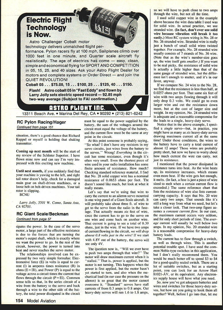
"Enclosed are pictures of a design I call the 'Q/D' (for Quick and Dirty). Fast and easy to build, but a little on the dirty side aerodynamically. The Q/D is actually the basic structure of my 3/4-scale, scratch-built Citabria Pro with a shoulder wing, 1,500 sq. in., and strip ailerons."
"Early this year, I had several weeks of radio problems and decided that I needed an expendable airplane for testing radios and new or repaired equipment. Thus was born the Q/D. The picture shows my wife, Donna, with the Q/D on floats designed by Ken Runestrand. This is the only way to fly during our Arizona summers."
One of the unique features of the Q/D is the method of attaching the wing. I use 1/4-in. plywood braces secured permanently to the wing which slip inside the fuselage sides when assembled. They are secured to the sides by 8-32 bolts inserted from the outside of the fuselage. There are two braces (one fore and one aft) on each side. The wing has a 1-in. aluminum spar tube, which is inserted into a hole in the 1/4-in. ply braces during wing construction. This assures that the braces will not separate from the wing. This construction survived a recent power-on dive into the lake by a Q/D owned by friend Scotty. (The transmitter antenna was not extended!)
Bill has plans available for the Q/D as well as for his DVIII and several other designs. I reviewed Bill's DVIII in my August 1981 column and, while I haven't seen the others, I assume they are up to the same high standard. If you are interested, write to:
- W. R. Wendt, 325 Buccaneer Lane, Lake Havasu City, AZ 86403
Wire Sizes Can Be a Safety Matter!
I recently got a letter from Ralph Warner of RAM (Radio Controlled Models, Inc.), who is anxious to point out the importance of adequate wiring in models, especially for large servos. Giant Scalers don't always understand the potential problems associated with large servos. In time we realize larger airframes mean larger loads; control-surface movement requires servos capable of delivering the needed torque. Keep in mind a servo doesn't produce electrical power — it converts electrical power to mechanical power. Increased power delivered by a servo takes the form of higher current flow from the battery.
Increased current drain means the battery needs to be larger in order to have the same operating time you get with standard batteries and standard servos. That increased drain is a battery-capacity consideration; you could simply plug in a larger battery system and forget about it. Unfortunately, that's just what a lot of people are doing, apparently unaware — or deliberately ignoring — other factors involved and the potential consequences: loss of servo power and/or disturbances to the rest of the system — glitches.
Let's look at the power-loss issue. Electrical power equals voltage times current. Since, for other reasons, we want to keep battery voltage nominally at 4.8 V (the same as smaller systems), we get extra power by using servos that draw higher current. As that current flows through the external circuit from one battery terminal to the other, it encounters resistance, which dissipates power. In the case of the servo motor, a large part of the effective resistance is due to the forces that are turning the motor's output shaft, which is where we want the power to go. In the rest of the circuit, however, the power is turned into heat and never reaches the servo motor.
Two basic formulas govern this:
- Electromotive force: E (volts) = I (amperes) × R (ohms) — E = I·R
- Power: P = E × I
Common sense tells us that in the series circuit of a wire from the battery to the servo and back, the total power dissipated must equal the power supplied by the battery; the sum of the voltages around the circuit equals the battery voltage; and the current flow is the same at any point in the circuit.
At this point someone might say, "I don't have any resistors in my servo circuits, just wires from the battery to the servos." Wrong: everything in the circuit has some resistance, even the shortest piece of wire. How much? Standard reference material shows No. 28 solid copper wire has a nominal resistance of about 0.0653 ohms per foot.
Example: using that wire to carry current to an aileron servo mounted in a wing panel will probably require about three feet of wire to get to the servo from the radio in the fuselage — actually six feet, because current must go to the servo on one wire and return on another. That current will see about 0.39 ohms just in the wire. If two amps flow in the circuit, nearly 0.8 volts will be dropped in the wire. Starting from 4.8 V at the battery, the servo would see only about 4.0 V.
When will we push two amps through that wire? The motor draws maximum current when it is stalled — when power is applied but the motor is not turning, which can happen when first powered or when the mechanical load is so great the motor cannot overcome it. Standard servos have stall currents from 0.3 A to 0.8 A. Heavy-duty servos run 1.0 A to 1.8 A, so you may need to push close to two amps through the wire, at least intermittently.
We normally use stranded wire (solid wire will break under vibration). Most RC wiring is No. 28 or No. 26 stranded wire. Stranded wire is a bundle of small solid wires twisted together; its resistance is slightly lower than the equivalent solid wire, but the difference is minor.
Compare No. 24 wire to No. 28: No. 24 has less than half the resistance, about 0.0257 ohms per foot. That same six feet of No. 24 with two amps flowing will only drop about 0.3 volts. You can go to larger wire for even lower resistance, but larger wire costs size and weight. In my opinion, No. 24 stranded wire is an adequate and practical compromise for single heavy-duty servos.
Note that while the example used a single servo, you might have as many as six heavy-duty servos drawing maximum current simultaneously. Under those conditions, the wires to the battery must carry a total current approaching 12 amps. Those wires are probably short, but now you must worry about current-carrying capacity, not just resistance.
Power dissipated in resistance turns into heat. As the wire heats, its resistance increases, which creates more heat; if hot enough, the wire melts. (A fuse is simply a wire sized to melt at a specified current.) Reference charts that list wire resistance also list current-carrying capacity. For example, the chart indicates No. 20 wire can carry about two amps — which might seem a reasonable compromise for heavy-duty servos. But current also has to flow through switches, another potential trouble spot.
I have used common Noble-type switches in this application, but I don't really recommend them. You would be better off spending $3–$4 for a good-quality sealed switch. There are many suitable switches; as a starting point look for Arrow Hart 81021-AV or an equivalent. Any electronics supply house can help.
Power Drops, Battery Internal Resistance, and Glitches
There is another hidden resistance we can't change: the internal resistance of the battery. Current supplied by the battery must flow through this internal resistance, and a small amount of voltage will be dropped across it (this is why battery voltage falls under load).
When servos draw heavy current as they start to move, that current through the battery's internal resistance causes the output voltage to drop momentarily. Depending on the current and condition of the battery, that drop could be as much as one volt — more than 20% of nominal battery voltage. Anything else connected to that battery will see that same drop. To the receiver and its decoder, that one-volt dip on their power supply can look like, or interfere with, legitimate signals. I am convinced this is the true source of many "glitches" reported when heavy-duty servos are used.
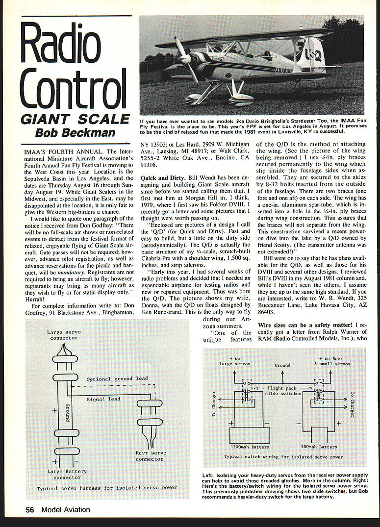
Isolating Heavy-Duty Servo Power
The solution is to isolate the heavy-duty servo power supply from the rest of the system. I have advocated this for several years. Every big bird I have built has had at least two large servos with long leads, but I have never had problems when their power was isolated. It means some added wiring and another switch, but that's a small price to pay for more reliable performance.
Basic technique:
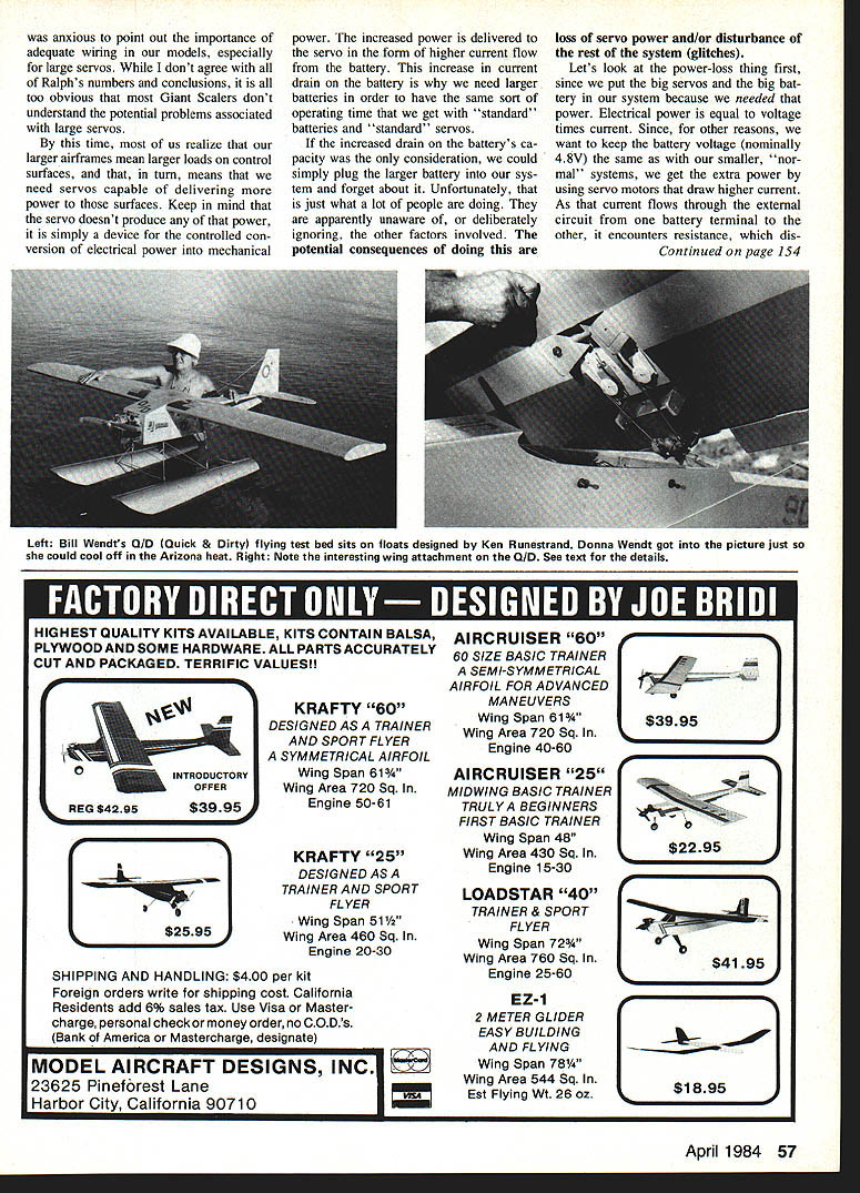
- Leave the standard receiver/switch/battery wiring and light-duty servos (throttle, ignition) as they are.
- Make special servo leads that take the servo control signal from the receiver as usual, but draw power from a separate heavy-duty battery.
- The control signal draws so little current that wire size for it is not critical; use larger wire, heavy-duty connectors, and an appropriately sized switch for power.
- For the small receiver-side connectors, cut a short aileron extender cable in half and splice the proper ends onto the heavy wire. At the receiver end there is no heavy current; the heavy current flows through the small wire only at the servo end, but if you keep that short (2–3 in.), it will work fine. While you're at it, shorten the leads on the servos.
- Use three-conductor, shielded cable with the shield connected to ground at the receiver end only (not at the servo end) to reduce noise pickup in the long leads. Cable for this purpose is available from electronics supply houses (e.g., Alpha No. 3212 three-conductor shielded cable or equivalent).
This may sound complicated at first, but it's simple once you get used to the technique. It is not a cure-all for every possible glitch, but it will make things smoother and safer for your big bird.
Bob Beckman 8248 Holly Grove Ct. Manassas, VA 22110
Transcribed from original scans by AI. Minor OCR errors may remain.

