
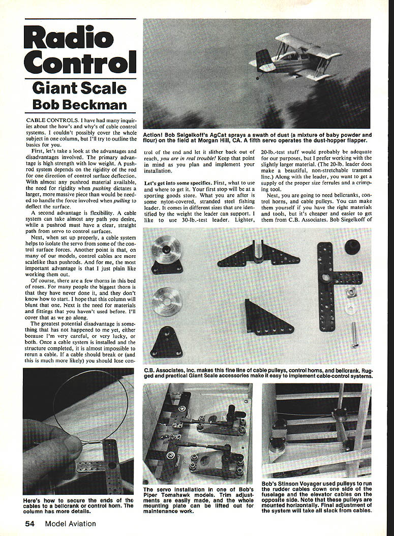
Radio Control: Giant Scale
Bob Beckman
Cable Controls
I have had many inquiries about the how's and why's of cable control systems. I couldn't possibly cover the whole subject in one column, but I'll try to outline the basics for you.
First, let's take a look at the advantages and disadvantages involved.
Advantages and disadvantages
- Advantages
- High strength with low weight. A pushrod system depends on the rigidity of the rod for one direction of control surface deflection. With almost any pushrod material available, the need for rigidity when pushing dictates a larger, more massive piece than would be needed to handle the force involved when pulling to deflect the surface.
- Flexibility. A cable system can take almost any path you desire, while a pushrod must have a clear, straight path from servo to control surface.
- When set up properly, a cable system helps isolate the servo from some of the control surface forces.
- Control cables are more scale-like than pushrods on many models.
- Personal preference: I like working with them.
- Disadvantages / cautions
- Many people are unfamiliar with cable systems and don't know how to start.
- You may need materials and fittings you haven't used before.
- Greatest potential disadvantage: once a cable system is installed and the structure completed, it is almost impossible to rerun a cable. If a cable should break (or — much more likely — you should lose control of the end and let it slither back out of reach), you are in real trouble. Keep that point in mind as you plan and implement your installation.
Materials and where to get them
Your first stop will be a sporting goods store. Look for nylon-covered, stranded steel fishing leader. It comes in different sizes identified by the weight the leader can support. I like to use 30-lb test leader. Lighter 20-lb test material would probably be adequate, but I prefer working with the slightly larger material. (The 20-lb leader does make a beautiful, non-stretchable trammel line.) Along with the leader, get a supply of the proper-size ferrules and a crimping tool.
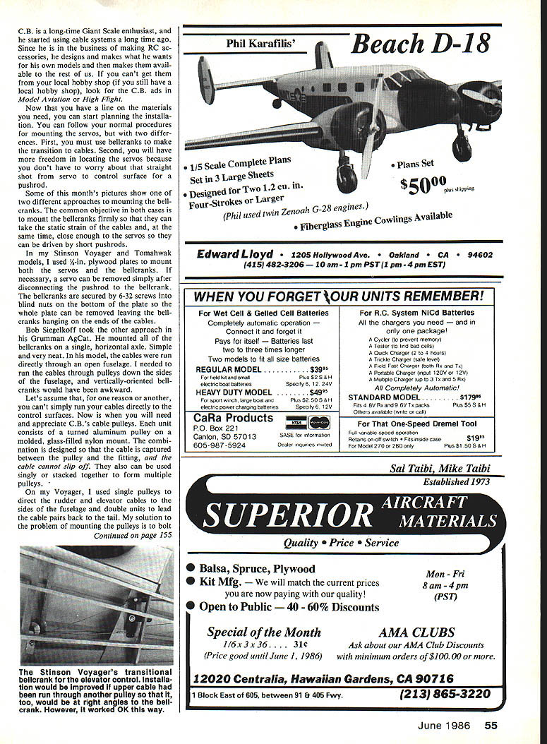
Next, you will need bellcranks, control horns, and cable pulleys. You can make them yourself if you have the right materials and tools, but it's cheaper and easier to get them from C.B. Associates. Bob Seigelkoff is a long-time Giant Scale enthusiast who started using cable systems a long time ago. Since going into business making R/C accessories, he designs and makes what he wants for his own models and makes them available to the rest of us who can't get them from the local hobby shop. If you still have a local hobby shop, look for C.B. Associates ads in Model Aviation and High Flight.
Mounting servos and bellcranks
You can follow normal procedures in mounting servos, with two differences:
- You must use bellcranks to make the transition to cables.
- You have freedom locating servos because you don't have to worry about a straight shot from servo to control surface as you do with a pushrod.
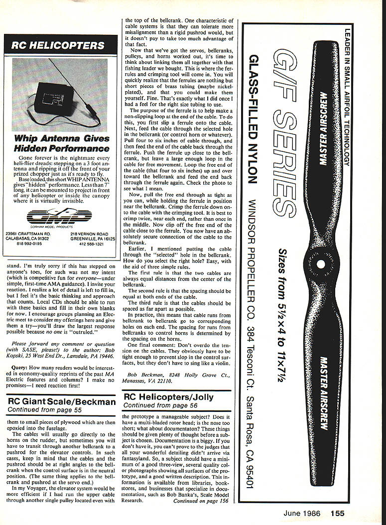
Some pictures show two different approaches to mounting bellcranks; the common objective in both cases is to mount bellcranks firmly so they can take the static strain of the cables and, at the same time, be close enough so the servos can be driven with short pushrods. On the Stinson Voyager and Tomahawk models, 1/8-in. plywood plates were used to mount both servos and bellcranks. When necessary, the servo can be removed simply after disconnecting the pushrod from the bellcrank. The bellcranks are secured with 6-32 screws and blind nuts to the bottom plate. The whole plate can be removed, leaving the bellcranks hanging on the ends of the cables.
Bob Seigelkoff took another approach on his Grumman AgCat, mounting bellcranks on a single horizontal axle. Simple and very neat. On that model the cables run directly through the open fuselage; if it had been necessary to run the cables through pulleys down the sides of the fuselage, vertically oriented bellcranks would have been awkward.
Pulleys
If you can't run the cables directly to the control surfaces, use C.B.'s cable pulleys. Each unit consists of a turned aluminum pulley on a molded, glass-filled nylon mount. The combination is designed so that the cable is captured between the pulley and the fitting, and the cable cannot slip off. They also can be used singly or stacked together to form multiple pulleys.
On my Voyager, I used single pulleys to direct the rudder and elevator cables to the sides of the fuselage and double units to lead the cable pairs back to the tail. My solution to the problem of mounting the pulleys is to bolt them to the top of the bellcrank. One characteristic of cable systems is that they can tolerate more misalignment than a rigid pushrod would, but it doesn't pay to take too much advantage of that fact.
Making cable loops and ferrules
Now that we've got the servos, bellcranks, pulleys, and horns worked out, it's time to think about linking them all together with the fishing leader we bought. This is where the ferrules and crimping tool will come in. The ferrules are nothing but short pieces of brass tubing (maybe nickel-plated), and you could make them yourself once you have a feel for the right size tubing to use.
The purpose of the ferrule is to make a non-slipping loop at the end of the cable. To do this:
- Slip a ferrule onto the cable.
- Feed the cable through the selected hole in the bellcrank (or control horn or whatever).
- Pull four to six inches of cable through, then feed the end of the cable back through the ferrule.
- Push the ferrule up close to the bellcrank, but leave a large enough loop in the cable for free movement.
- Loop the free end of the cable (that four to six inches) up and over toward the bellcrank and feed the end back through the ferrule again.
- Pull the free end through as tight as you can while holding the ferrule in position near the bellcrank.
- Crimp the ferrule down onto the cable with the crimping tool. It is best to crimp twice, near each end, rather than once in the middle.
- Clip off the free end of the cable close to the ferrule.
You now have an absolutely secure connection of the cable to the bellcrank.
Selecting bellcrank holes
How do you select the right hole in the bellcrank? Use three simple rules:
- The two cables are always equal distances from the center of the bellcrank.
- The spacing should be equal at both ends of the cable.
- The cables should be spaced as far apart as possible.
In practice, cable runs from bellcrank to bellcrank go to corresponding holes on each end. The spacing for runs from bellcranks to control horns is determined by the spacing on the horns.
Final tips
Don't overdo the tension on the cables. They obviously have to be tight enough to prevent slop in the control surfaces, but they don't have to sing like a violin.
Bob Beckman 8248 Holly Grove Ct. Manassas, VA 22110.
Transcribed from original scans by AI. Minor OCR errors may remain.

