
Radio Control: Giant Scale
Bob Beckman
SPARROWHAWK aileron hinges
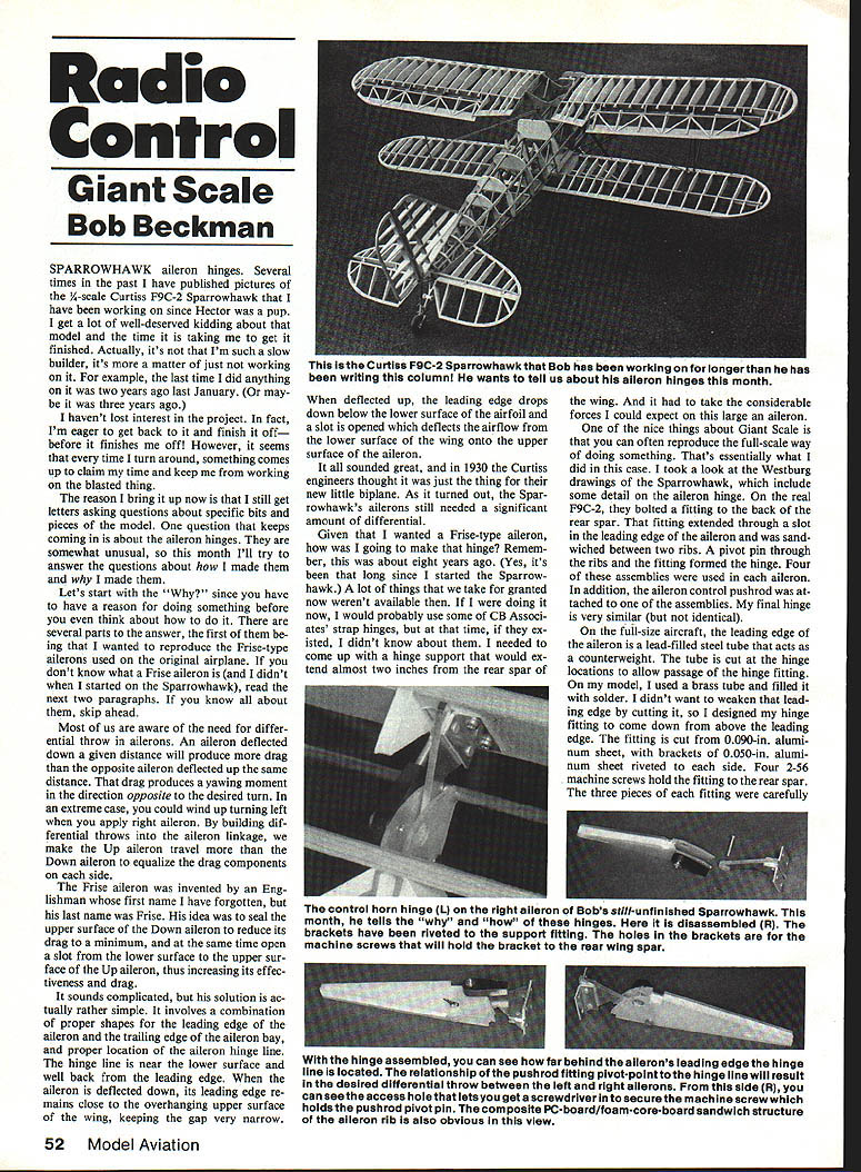
Several times in the past I have published pictures of the 1/4-scale Curtiss F9C-2 Sparrowhawk that I have been working on since Hector was a pup. I get a lot of well-deserved kidding about that model and the time it is taking me to get it finished. Actually, it's not that I'm such a slow builder; it's more a matter of just not working on it. For example, the last time I did anything on it was two years ago last January. (Or maybe it was three years ago.)
I haven't lost interest in the project. In fact, I'm eager to get back to it and finish it off—before it finishes me off! However, it seems that every time I turn around, something comes up to claim my time and keep me from working on the blasted thing.
The reason I bring it up now is that I still get letters asking questions about specific bits and pieces of the model. One question that keeps coming in is about the aileron hinges. They are somewhat unusual, so this month I'll try to answer the questions about them and why I made them.
Let's start with the "Why?" since you have to have a reason for doing something before you even think about how to do it. There are several parts to the answer, the first of them being that I wanted to reproduce the Frise-type ailerons used on the original airplane. If you don't know what a Frise aileron is (and I didn't when I started on the Sparrowhawk), read the next two paragraphs. If you know all about them, skip ahead.
Most of us are aware of the need for differential throw in ailerons. An aileron deflected down a given distance will produce more drag than the opposite aileron deflected up the same distance. That drag produces a yawing moment in the direction opposite to the desired turn. In an extreme case, you could wind up turning left when you apply right aileron. By building differential throws into the aileron linkage, we make the up aileron travel more than the down aileron to equalize the drag components on each side.
The Frise aileron was invented by an Englishman whose first name I have forgotten, but his last name was Frise. His idea was to seal the upper surface of the down aileron to reduce its drag to a minimum, and at the same time open a slot from the lower surface to the upper surface of the up aileron, thus increasing its effectiveness and drag.
It sounds complicated, but his solution is actually rather simple. It involves a combination of proper shapes for the leading edge of the aileron and the trailing edge of the aileron bay, and proper location of the aileron hinge line. The hinge line is near the lower surface and well back from the leading edge. When the aileron is deflected down, its leading edge remains close to the overhanging upper surface of the wing, keeping the gap very narrow. When deflected up, the leading edge drops down below the lower surface of the airfoil and a slot is opened which deflects the airflow from the lower surface of the wing onto the upper surface of the aileron.
It all sounded great, and in 1930 the Curtiss engineers thought it was just the thing for their new little biplane. As it turned out, the Sparrowhawk's ailerons still needed a significant amount of differential.
Given that I wanted a Frise-type aileron, how was I going to make that hinge? Remember, this was about eight years ago. (Yes, it's been that long since I started the Sparrowhawk.) A lot of things that we take for granted now weren't available then. If I were doing it now, I would probably use some of CB Associates' strap hinges, but at that time, if they existed, I didn't know about them. I needed to come up with a hinge support that would extend almost two inches from the rear spar of the wing to the leading edge of the aileron and take the considerable forces one could expect from a large aileron. The nice thing about Giant Scale is we can often reproduce full-size ways of doing something. That's essentially what I did in this case.
I took a look at the Westburg drawings of the Sparrowhawk, which include some detail on the aileron hinge. On the real F9C-2, they bolted a fitting to the back of the rear spar. That fitting extended through a slot in the leading edge of the aileron and the aileron was sandwiched between two ribs. A pivot pin through the ribs and the fitting formed the hinge. Four of these assemblies were used in each aileron. In addition, the aileron control pushrod was attached to one of the assemblies.
My final hinge was similar (but not identical).
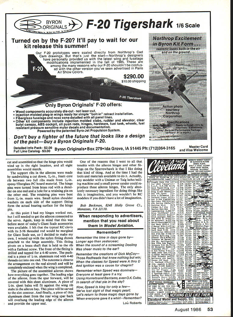
On the full-size aircraft, the leading edge of the aileron is a lead-filled steel tube that acts as a counterweight. The tube is cut at the hinge locations to allow passage of the hinge fitting. On my model, I used a brass tube and filled it with solder. I didn't want to weaken that leading edge by cutting it, so I designed my hinge fitting to come down above the leading edge. The fitting is cut from 0.090-in. aluminum sheet, with brackets of 0.050-in. aluminum sheet riveted to each side. Four 2-56 machine screws hold the fitting to the rear spar. The three pieces of each fitting were carefully cut and assembled so that the hinge pins would wind up in the right location, and all eight assemblies would match.
The support ribs in the ailerons were made by sandwiching a cut-down 3/16-in. foam-core rib between two full ribs made from 3/32-in. epoxy/fiberglass PC board material. The hinge pins were turned from brass rod with a shoulder on one end and a hole for a retaining pin on the other end. The retaining pins were bent from 1/32-in. music wire. Small nylon shoulder washers on each side of the support fitting form the actual bearing surface for the hinge pin.
At this point I had my hinges worked out, but I still needed to get the aileron connected to the servo. Again, keep in mind that this was before most of today's Giant Scale accessories were available. I felt that the typical RC clevis with its 2-56 threaded rod would be marginal for Giant Scale use, so I decided to make my own. I wound up with the nylon fitting shown attached to the hinge assembly. This fitting pivots on a brass shaft that is held to the rib with a flathead screw. The front of the fitting is drilled and tapped for a 4-40 screw. The pushrod is a piece of 1/8-in. aluminum rod with 4-40 threads cut into one end. The outcome is close to the arrangement on the real aircraft and will be completely enclosed when the wing is completed.
The picture of the assembled aileron shows how everything goes together. The leading edge of the aileron, from the spar forward, will be covered with thin sheet aluminum. A piece of 1/16-in. sheet balsa will fit against the wing rib stubs in the aileron bay. This piece will be carved to the slot contour. And finally, a piece of thin aluminum sheet from the rear wing spar back will overhang the leading edge of the aileron and provide the upper seal.
One of the reasons that I went to all that trouble with the aileron hinges and other fittings on the Sparrowhawk is that I like doing that kind of thing. And at the time I had the tools and materials available to do it. Actually, any modeler with a Unimat or Taig lathe/milling machine and a small power sander could reproduce these aileron hinges. The only absolutely necessary ingredient for doing things like this is imagination, and you wouldn't be RC modelers if you didn't have a lot of imagination.
Bob Beckman 8248 Holly Grove Ct. Manassas, VA 22110
Transcribed from original scans by AI. Minor OCR errors may remain.

