

Radio Control: Giant Scale
John A. de Vries Colonel, USAF, Ret.
Redundancy is the key word this month. Giant Scale models usually can carry a bit of extra weight, which lets us add redundant equipment to make the airplanes much safer to fly. Below are practical redundancy measures and installation tips that have proven effective for Big Birds.
Servos and control surfaces
Early Giant builders found it necessary to double up servos on flying surfaces to prevent air loads from blowing controls down. Practical approaches include:
- Separate servos for each aileron (dual servos).
- Dual servos for rudder and elevators.
- Paralleling pushrods where appropriate to provide a backup mechanical path.
Note: Y-connected servos require long lead runs, which can pick up RF interference. This is commonly solved by installing ferrite chokes on the long leads to suppress noise and preserve reliable control response.
Batteries and receivers
The Ni-Cd receiver/servo battery pack is often the weakest link in the radio chain. Redundant power and receivers dramatically increase flight reliability:
- Use twin 1,200 mAh receiver/servo batteries with an automatic switch-over in case one pack fails.
- Install two receivers when practical. They can be tuned to the same transmitter or, in more robust setups, to a second backup transmitter.
- Physically separate the receivers as far apart inside the airframe as possible to minimize mutual interference, especially if operating on two frequencies.
Combining twin receivers with dual batteries creates a nearly totally redundant radio system while adding only nominal weight (often a pound or less).
Control-system partitioning and redundancy techniques
There are several ways to divide control responsibilities between systems to maximize survival of partial failures:
- Assign one receiver/system to control one side of the elevator and the other to the opposite side. This is particularly effective on larger Giants.
- Use dual rudder servos with cross-assigned functions: one servo’s primary function could be the tailwheel and secondary the rudder, while the other servo’s primary is the rudder and secondary the tailwheel.
- Consider dual servos on ailerons when weight and geometry allow.
For complete redundancy, consider closed-loop cable control systems:
- Connect both sides’ servo control arms to the control-surface horns as in prototype installations. Loss of a single cable then has minimal effect.
- Expect more complex routing: four cable terminations at servo arms (e.g., two Ups and two Downs for an elevator), extra pulley wheels, paired pulleys, and bellcrank idlers to keep servo-to-bellcrank runs short and clean.
- Follow prototype practice where possible when paralleling wires through paired pulleys.
Engines and ignition safety
Engine reliability and ignition safety are also ripe for redundancy:
- For two-stroke (glow) engines, install a second glow plug and a microswitch that disables it at idle. This helps keep the engine lit during idle and ensures reliable acceleration after an idling descent.
- For gasoline engines, follow IMAA safety rules that mandate a servo-operated mixture control (in the ignition circuit). Many builders add a secondary manual cutoff button that grounds the ignition circuit as an emergency kill.
- Provide a manual ignition cutoff that can be reached safely from outside the model. A simple, accessible manual switch is a highly recommended redundancy and safety measure.
Transmitter and operator-side redundancy
Simple, low-cost transmitter redundancy can be very effective:
- As implemented by Ed Carroll, add diodes, a plug, and a switch to allow a second battery pack to be connected to the transmitter. Switching to the spare pack mid-day refreshes power without recharging.
- Secure the spare transmitter pack with Velcro to the back of the transmitter case for portability and convenience.
Final notes and credit
Redundancy need not be complicated or heavy. Thoughtful placement and partitioning of servos, receivers, batteries, cables, and switches will significantly increase the probability of a successful flight.
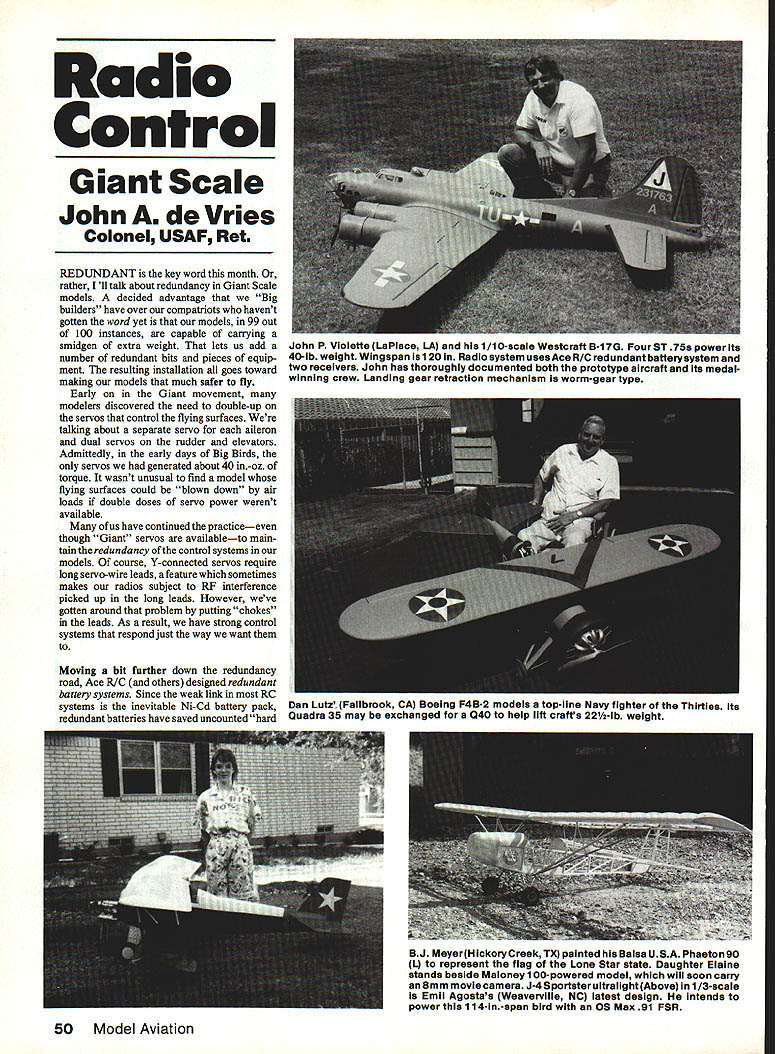
Credit for inspiration for this column goes to John P. Violette of LaPlace, LA, whose magnificent B-17G model and its documented prototype history are featured with this issue.
Transcribed from original scans by AI. Minor OCR errors may remain.

