
RADIO CONTROL GIANTS
John A. de Vries, 4610 Moffat Lane, Colorado Springs, CO 80915
Foam, foam on the range—or words to that effect. There are two schools of thought about using polystyrene foam to construct RC models and Giant Scale models in particular.
The first group feels that using foam produces models that are heavier than they need to be. The second considers foam to speed model construction, provide wings that maintain their airfoil better from root to tip, and accepts the slight increase in weight as a necessary evil.
I lean toward the second school of thought. There are many model-building situations where foam may be used to good effect, not all of which pose an unreasonable weight penalty. The following three examples illustrate the contention.
Examples of foam use
- Foam to produce fiberglass masters and plugs
- Polystyrene foam (the blue variety in particular) may be used to produce fiberglass masters (or plugs), from which fiberglass model parts may be cast.
- Laminated into large blocks, entire fuselages may be carved, sanded, or hot-wired in short order.
- It does take a degree of skill to remove all the foam that doesn't look like the fuselage for the scale model you intend to produce. Since foam is relatively inexpensive, a second try won't cost much if you goof on your first attempt at foam sculpting.
- Minor dings or major contour errors may be corrected by cutting out the offending portions, inserting a fresh foam block or lamination, and reworking the area. Most of this may be accomplished using nothing other than varying grits of sandpaper.
If your intention is to produce a female fiberglass mold from your foam "solid" model, two things must be considered:
- First, the centerline of your foam part should fall between two foam laminations, and sheets of paper should be inserted between them before you begin carving. Thus, splitting the resulting fuselage into symmetrical halves should be uncomplicated.
- Second, the completed foam part should be sealed and smoothed with a foam-compatible filler. Japanese tissue sealed in place, followed by several coats of filler—after dedicated sanding—will produce an ideal, glass-smooth subject for producing a two-part mold.
Good friend George Fisher was an advocate of this technique and used it to produce a quarter-scale model of Art Chester's Goon. George went so far as to make the entire fuselage, from spinner to rudder post, in one piece. He built a crutch assembly to accept the firewall, wing and stabilizer supports, and retractable landing gear shelf inside the completed fiberglass fuselage. A cut along the scale rear cowl line made it simple to insert the structural crutch and epoxy it in place.
- Composite foam wing — Martin B-10 bomber (115-inch span)
- About 12 years ago I designed a 115-inch-span Martin B-10 bomber that has a composite foam wing.
- The wing's rectangular (in planform) center section, which supports the two engine nacelles and retractable landing gear assemblies, consists of balsa ribs and plywood spars and is intended to be built into the model's fuselage.
- The wing panels outboard of the engine nacelles are pure, wood-skinned foam with balsa tips. They include balsa spars to hold the aileron hinges and only have to be grooved for aileron linkages and reinforced with carbon tape under the skin. The outer panels have plug-in metal tubes to facilitate transportation.
- The beauty of the design was that I only had to draw two wing ribs—the fixed center portion of the wing was of constant section and could be used for the inner rib for hot-wiring the outer panels. The second rib was the tip rib, needed to complete the wing panel cuts.
- Foam-skinned fuselage top — Percival Mew Gull kit
- I purchased a British kit for a large Percival Mew Gull. The top of the fuselage, from the cowl aft to the cockpit and the entire turtledeck (from the cockpit aft to the rudder post), was devoid of any compound curves.
- The kit manufacturer hot-wired both pieces from foam and laminated their outer surfaces using thin plywood.
- When the basic fuselage box was built up using 1/8-inch-square balsa, the fuselage top only had to be glued in place to complete it. This saved significant time and effort.
Foam, used by itself or as part of a composite model structure, is an integral part of today's modeling scene. A few extra ounces in a Giant Scale model is easily accommodated if you decide to use it.
Radio installation and protecting receivers and batteries
It's a given that most Giant Scale models have space out the wazoo for radio installation. When using the monster servos to which many of us are addicted, there's usually a vast cavern inside our models. That poses the problem of how to protect the most sensitive parts of our airborne radio set: the receiver and the battery.
Because servos are mounted with rubber grommets to protect them from engine vibration, the usual technique for isolating the receiver and battery involves wrapping them in foam rubber, placing them in plastic bags, then burying them in a foam nest to keep them from rattling around. I wish I had a nickel for every cubic inch of foam rubber that's been used to fill receiver caverns in Giant Scale models!
LDM Industries, Inc. (P.O. Box 292396, Tampa, FL 33687–2396) has come up with a very sanitary way to protect receivers and flat battery packs. They call it the Strongbox II, and it's the answer to a model builder's prayer.
Strongbox II — features and specs
- The Strongbox II consists of two molded plastic shells filled with several layers of foam. You make a cutout in one layer for your receiver and another in a layer beneath it for the battery pack.
- The cutout process is similar to that employed in today's camera and gun cases.
- There is an aperture in one end of the plastic cover to accept servo wire leads, and a hole drilled in the top of the case to accommodate the exit of the receiver's antenna. A bit of plastic serves as a strain relief for the antenna as part of the assembly.
- With everything tucked neatly inside, the top and bottom portions of the Strongbox II are held together with three screws (provided). There are four mounting holes molded into the bottom of the box so that the whole assembly can be mounted to rails in your Giant Scale model's fuselage.
- Dimensions and weight: 3.3 inches wide, 3.5 inches deep, 6.2 inches long, and weighs a mere four ounces.
- With the Strongbox assembled, it would take a house falling on your model to flatten your RC receiver—or at least a Mach 1 crash!
IMAA Rally of the Giants — 1994
IMAA's Larry Wheat is the Rally Coordinator for the 1994 Rally of the Giants. The IMAA's big gathering of the year will be held at the Arlington Municipal Airport, Arlington, Washington (north of Seattle).
The 1994 rally is scheduled for July 15–17 and will be sponsored by the Boeing Recreation folks, the Boeing Hawks R/C Flyers, IMAA Chapter #163, and Puget Sound R/C Clubs. For information, contact Larry at 26214 42 Ave. S.E., Kent, WA 98032; Tel.: (206) 477-1603 until 2:30 PST, or (206) 852-6502 after 3:30 PST. Make your plans to attend now.
Model builder spotlight
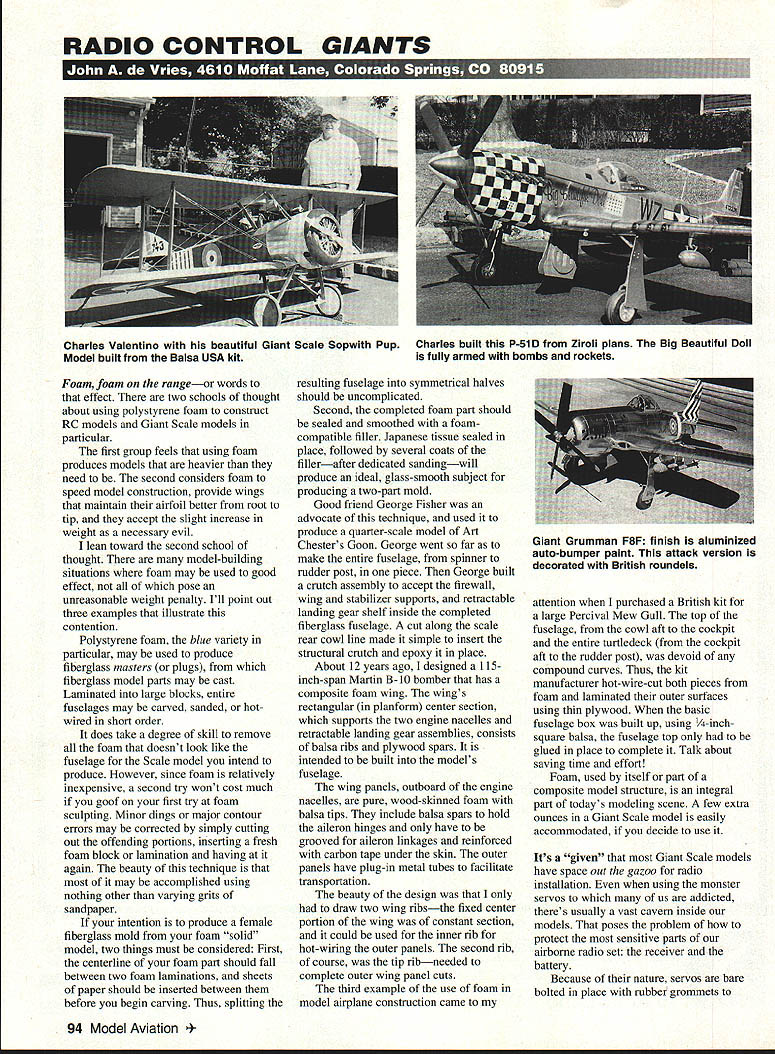
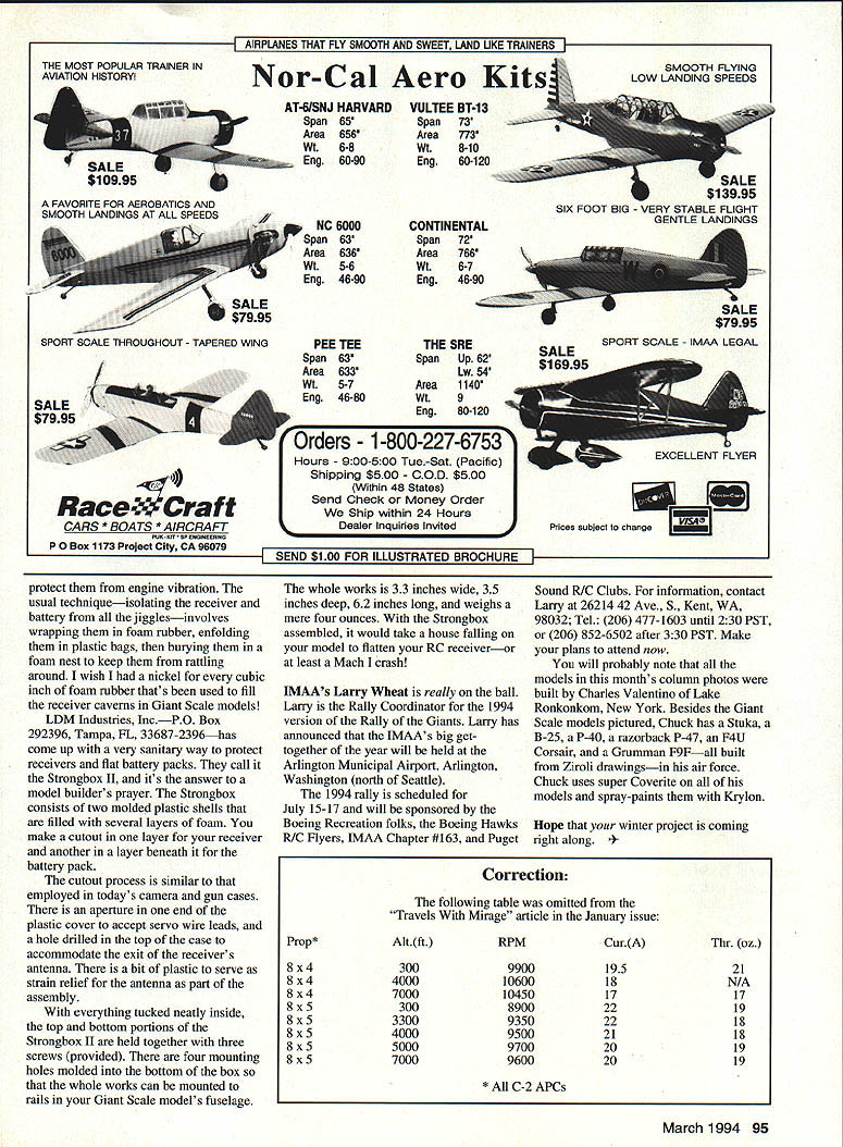
All the models in this month's column photos were built by Charles Valentino of Lake Ronkonkoma, New York. Besides the Giant Scale models pictured, Chuck has a Stuka, a B-25, a P-40, a razorback P-47, an F4U Corsair, and a Grumman F9F—all built from Ziroli drawings—in his attic. Chuck uses Super Coverite on all of his models and spray-paints them with Krylon.
Hope that your winter project is coming right along.
Transcribed from original scans by AI. Minor OCR errors may remain.

