
RADIO CONTROL GIANTS
John A. de Vries 4610 Moffat Lane, Colorado Springs, CO 80915
Documentation and John Meyer’s AT-6 Texan
It isn't news to a scale model builder that you need documentation for your model—preferably before you begin construction. Collecting documentation amounts to a research project that often continues even after the model is completed and flying. Most of the data collected isn't required, but it often fills notebook after notebook. The amount of detail can come as a surprise to someone called upon to provide documentation for a builder who was working on a 1:1 scale aircraft: John Meyer telephoned from Seattle, and his project is the complete rehabilitation of a North American AT-6 Texan.
The Texan is a very particular aircraft. Soon after it was manufactured it was assigned to the Instrument Training Group at Craig Field, Selma, Alabama, as aircraft number 522. It was unique because it was equipped at the factory with an Automatic Direction Finder (ADF).
With the exception of the AT-6s at the Instrument Instructors School (Bryan, Texas), the Craig Field instrument-instruction aircraft were the only North American trainers with the ADF loop installed during World War II in the usual "football" fairing. The loop was located between the cockpit and the rudder, atop the fuselage.
John's documentation included the article I wrote about the Texan for Paul Matt's Historical Aviation Album. In it I noted that I'd been an instrument instructor at Craig Field, and he correctly assumed that I may have flown #522 in the 1940s.
John hopped on an airliner and visited me on a Saturday in March. I learned that he had disassembled #522 and was building it back up as new. His construction photos showed the basic fuselage structure bare on his workbench.
John and I had a rather intense three-hour session. His basic questions concerned the markings of Craig Field instrument trainers, the location of the ADF "football," and where the ADF control boxes were mounted in the aircraft's cockpits. Having flown the AT-6 for about 1,200 hours, I certainly remembered where things were located.
When John returned to Seattle he examined the tail cone more carefully and found the teardrop-shaped ADF loop mounting pad that had been patched over by a previous owner.
John had flown his AT-6 before breaking it down for reconstruction and had the engine completely "majored" so that it ran like a sewing machine.
I was very happy to help with the documentation of John's full-scale aircraft, and I'm looking forward to the Meyer Texan in its original Craig Field instrument-trainer colors and numbers. You can't get any more Giant Scale than that!
Giant Scale bombers and a personal B-17
Most Giant Scalers—particularly when they are new to the hobby—have an urge to build a B-17 or a B-24. Both World War II bombers have an attraction, despite the complexities that a four-engined radio-control (RC) model proposes.
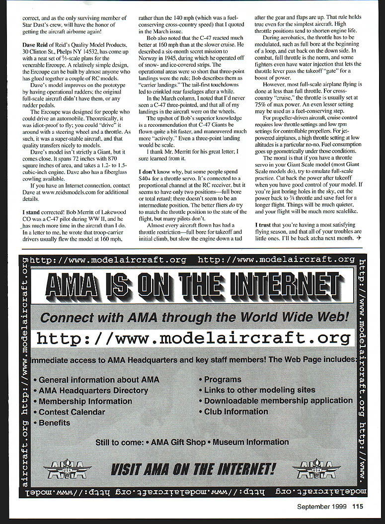
However, when a seasoned Giant Scale modeler has the inspiration to create a miniature airplane that duplicates "his" WWII airplane, the urge is irresistible. That was the situation facing Gren Hawes of Olympia, Washington, who served as the tailgunner on Star Dust, a B-17 Flying Fortress.
Number 42-39901 completed 13 missions in late 1943 and early 1944 before it was crippled by flak and lost two engines over France. The Fortress made it back to England, where it crash-landed in a field. Only one crew member was injured.
The basic Hawes B-17 model was furnished as an English Aerotech International kit. Key facts about the model:
- Scale: 1/12
- Wingspan: 104 inches
- Completed weight: 29 pounds
- Power: four O.S. FP .40 engines
- Radio: five-channel JR
- Servos: 11
Gren has flown the bomber long enough to know that the center of gravity is too far aft. He figures that it will be easy to correct.
Reid’s Ercoupe 1/5-scale plans
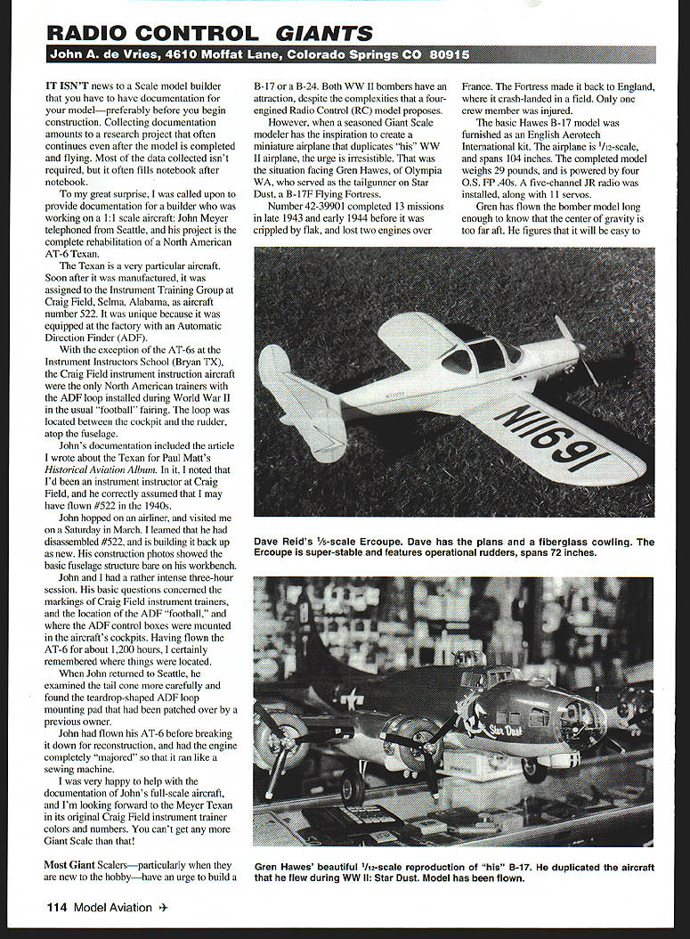
Dave Reid, Reid's Quality Model Products, has come up with neat 1/5-scale plans for the venerable Ercoupe, a relatively simple design. The Ercoupe can be built by almost anyone who has glued together a couple of RC models. Dave's model improves on the prototype by having operational rudders—the original full-scale aircraft didn't have rudder pedals.
The Ercoupe was designed so people could drive to the airport in an automobile; theoretically idiot-proof to fly, one could taxi around by steering wheel and throttle. As such, the super-stable qualities transfer nicely to models.
Model specs:
- Wingspan: 72 inches
- Wing area: 870 square inches
- Engine: 12–15 cubic-inch
- Optional: fiberglass cowling available
For additional details contact Reid's Quality Model Products, 30 Clinton St., Phelps, NY 14532 or via the Internet at www.reidsmodels.com.
C-47 three-point landings — Bob Merritt
Stand corrected. Bob Merritt of Lakewood, Colorado, a C-47 pilot during WWII, has much time in the aircraft. In a letter he wrote that troop-carrier drivers usually flew the C-47 at 160 mph rather than 140 mph for fuel-conserving cross-country flights. Bob also noted that the C-47 reacted much better at 160 mph than at the slower cruise.
He described a six-month secret mission to Norway in 1945, during which he operated off snow- and ice-covered strips. The operational areas were so short that three-point landings were the rule; Bob describes them as "carrier landings." The tail-first touchdowns led to crinkled rear fuselages after a while.
In the March column I noted that I'd never seen a C-47 three-point, and that all of my landings in the aircraft were on the wheels.
The upshot of Bob's superior knowledge is a recommendation that C-47 Giants be flown quite a bit faster, and maneuvered much more "actively." Even a three-point landing would be scale. I thank Mr. Merritt for his great letter; I sure learned from it.
Throttle use in Giant Scale models
I don't know why, but some people spend $40+ for a throttle servo. It's connected to a proportional channel at the RC receiver, but it seems to have only two positions—full bore or total retard; there doesn't seem to be an intermediate position. The better fliers do try to match the throttle position to the state of the flight, but many pilots don't.
Almost every aircraft flown has had a throttle restriction—full bore for takeoff and initial climb, then slow the engine down a tad after the gear and flaps are up. That rule holds true even for the simplest aircraft. High throttle positions tend to shorten engine life.
During aerobatics, the throttle has to be modulated—for example, full bore at the beginning of a loop and cut back on the down side. In combat, full throttle is the norm, and some fighters even have water injection that lets the throttle lever pass the takeoff "gate" for a boost of power.
However, most full-scale airplane flying is done at less than full throttle. For cross-country "cruise," the throttle is usually set at about 75% of max power. An even lesser setting may be used as a fuel-conserving step.
- For propeller-driven aircraft with controllable-pitch props, cruise control requires low throttle settings and low RPM settings.
- For jet-powered airplanes, a high throttle setting at low altitudes is a particular no-no—fuel consumption goes up geometrically under those conditions.
The moral: if you have a throttle servo in your Giant Scale model (most Giant Scale models do), try to emulate full-scale practice. Cut back the power after takeoff when you have good control of your model. If you're just boring holes in the sky, cut the power back to 3/4 throttle and save fuel for a longer flight. Things will be much quieter, and your flight will be much more scale-like.
Closing
I trust that you're having a most satisfying flying season, and that all of your troubles are little ones. I'll be back atcha next month.
Transcribed from original scans by AI. Minor OCR errors may remain.

