
Radio Control: Helicopters
Walt Schoonard
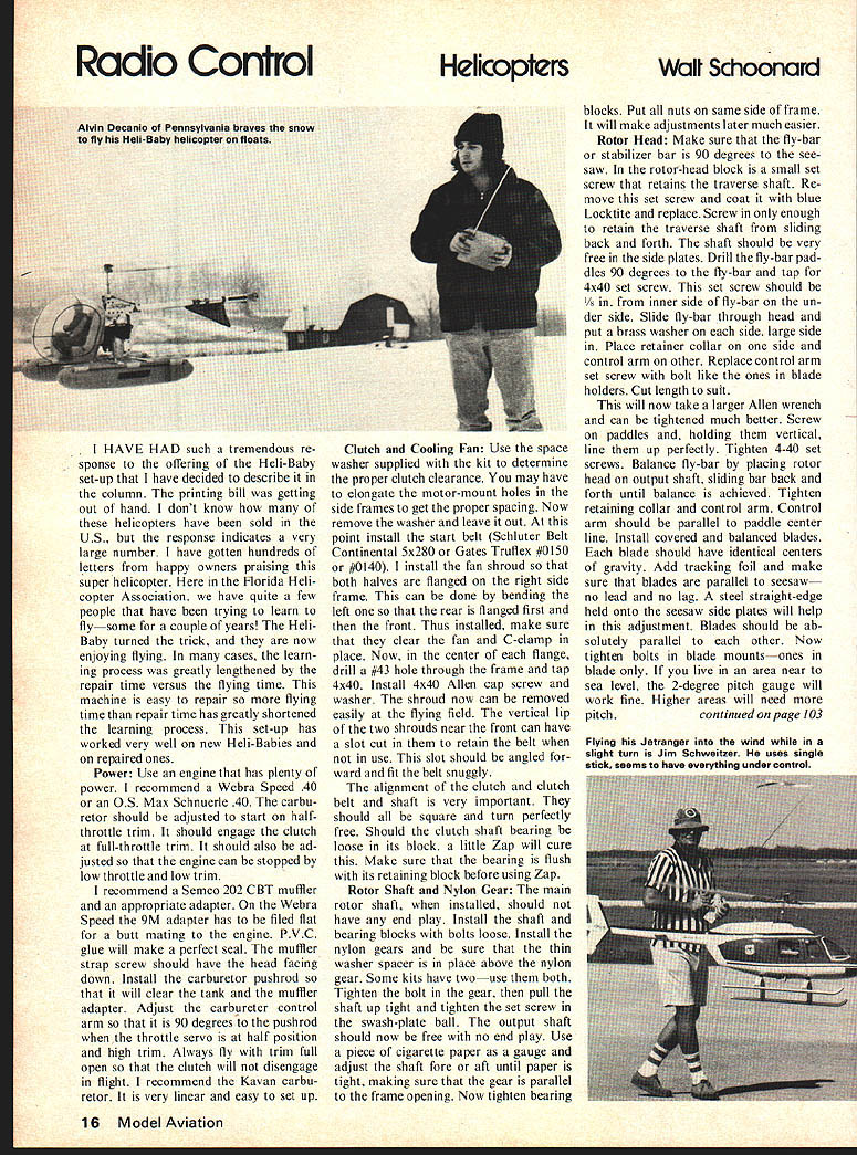
I HAVE HAD such a tremendous response to the offering of the Heli-Baby set-up that I have decided to describe it in the column. The printing bill was getting out of hand. I don't know how many of these helicopters have been sold in the U.S., but the response indicates a very large number. I have gotten hundreds of letters from happy owners praising this super helicopter. Here in the Florida Helicopter Association, we have quite a few people that have been trying to learn to fly—some for a couple of years! The Heli-Baby turned the trick, and they are now enjoying flying. In many cases, the learning process was greatly lengthened by the repair time versus the flying time. This machine is easy to repair so more flying time than repair time has greatly shortened the learning process. This set-up has worked very well on new Heli-Babies and on repaired ones.
Power
Use an engine that has plenty of power. I recommend a Webra Speed .40 or an O.S. Max Schnuerle .40. The carburetor should be adjusted to start on half-throttle trim. It should engage the clutch at full-throttle trim. It should also be adjusted so that the engine can be stopped by low throttle and low trim.
I recommend a Semco 202 CBT muffler and an appropriate adapter. On the Webra Speed the 9M adapter has to be filed flat for a butt mating to the engine. P.V.C. glue will make a perfect seal. The muffler strap screw should have the head facing down. Install the carburetor pushrod so that it will clear the tank and the muffler adapter. Adjust the carburetor control arm so that it is 90 degrees to the pushrod when the throttle servo is at half position and high trim. Always fly with trim full open so that the clutch will not disengage in flight. I recommend the Kavan carburetor. It is very linear and easy to set up.
Clutch and Cooling Fan
Use the space washer supplied with the kit to determine the proper clutch clearance. You may have to elongate the motor-mount holes in the side frames to get the proper spacing. Now remove the washer and leave it out. At this point install the start belt (Schluter Belt Continental 5x280 or Gates Truflex #0150 or #0140). I install the fan shroud so that both halves are flanged on the right side frame. This can be done by bending the left one so that the rear is flanged first and then the front. Thus installed, make sure that they clear the fan and C-clamp in place. Now, in the center of each flange, drill a #43 hole through the frame and tap for 4x40. Install 4x40 Allen cap screw and washer. The shroud now can be removed easily at the flying field. The vertical lip of the two shrouds near the front can have a slot cut to retain the belt when not in use. This slot should be angled forward to fit the belt snugly.
The alignment of the clutch and clutch belt and shaft is very important. They should all be square and turn perfectly free. Should the clutch shaft bearing be loose in its block, a little Zap will cure this. Make sure that the bearing is flush with its retaining block before using Zap.
Rotor Shaft and Nylon Gear
The main rotor shaft, when installed, should not have any end play. Install the shaft and bearing blocks with bolts loose. Install the nylon gears and be sure that the thin washer spacer is in place above the nylon gear. Some kits have two—use them both. Tighten the bolt in the gear, then pull the shaft up tight and tighten the set screw in the swash-plate ball. The output shaft should now be free with no end play. Use a piece of cigarette paper as a gauge and adjust the shaft fore and aft until paper is tight, making sure that the gear is parallel to the frame opening. Now tighten bearing blocks. Put all nuts on same side of frame. It will make adjustments later much easier.
Rotor Head
Make sure that the fly-bar or stabilizer bar is 90 degrees to the seesaw. In the rotor-head block is a small set screw that retains the traverse shaft. Remove the set screw and coat it with blue Locktite and replace. Screw in only enough to retain the traverse shaft from sliding back and forth. The shaft should be very free in the side plates. Drill the fly-bar paddles 90 degrees to the fly-bar and tap for 4x40 set screw. This set screw should be 1/8 in. from inner side of fly-bar on the under side. Slide fly-bar through head and put a brass washer on each side, large side in. Place retainer collar on one side and control arm on other. Replace control arm set screw with a bolt like the ones in blade holders. Cut length to suit. This will now take a larger Allen wrench and can be tightened much better. Screw paddles and, holding them vertical, line them up perfectly. Tighten 4-40 set screws.
Balance fly-bar by placing rotor head output shaft and sliding bar back and forth until balance is achieved. Tighten retaining collar and control arm. Control arm should be parallel to paddle center line. Install covered and balanced blades. Each blade should have identical centers of gravity. Add tracking foil and make sure blades are parallel to the seesaw—no lead or lag. A steel straight-edge held onto seesaw side plates will help this adjustment. Blades should be absolutely parallel to each other. Now tighten bolts in blade mounts—ones in blade area near sea level. A 2-degree pitch gauge will work fine. Higher areas will need more pitch.
RC Helicopters/Schoonard
Attach gauge to blade with small rubber band. Thick part to leading edge, sight across the fly-bar, bring the lower side of gauge horizontal to fly-bar. Carefully tighten pitch bolts on seesaw and recheck pitch. Make sure that both blades are the same. Remove entire rotor system from output shaft and support head by fly-bar on two parallel surfaces. Drill end of heavy blade; if this is not enough, add weight to light blade end. Small brads driven into the blade end do fine. When balanced perfectly, install rotor head on output shaft and tighten bolt. Turn the collector over so that small part faces down and compress spring on swashplate. Distance from level swash-plate to nearest part of the collector should be 35 mm.
Swash-Plate: With servos in neutral, radio and transmitter on, and all trims in neutral, the swash-plate should be adjusted so that it is 90 degrees to output shaft all the way around. Adjust servo-throw so that swash-plate will tilt at least 10 mm. up or down, right or left. Now adjust control rod to fly-bar so that fly-bar control lever is even to swash-plate, and paddles are horizontal.
Tail Rotor: The tail rotor is turning the same speed as the motor so some special care will need to be taken in this area. The tail rotor blades should have a 1/32" plywood reinforcement epoxied onto the backside in the holder area. Cover or paint the blades and balance them carefully. The pitch-control arm should slide very easily through the tail-rotor shaft. It should also rotate freely in the pitch-angle plate. Do not open up the slot. It should, however, be free of burrs. By bending the front edge up and the rear down, the pitch-angle plate will let the rod move from end to end. Your servo should give you at least 90 percent travel in this slot.
A Kavan blade-balance collar should be placed on each side of the tail-rotor shaft next to the needle bearings to transfer the wear point outside, so that it can be lubricated each flight without getting the belt oily.
A small washer should be placed on each side of the nylon pitch plate to keep it from heating up and melting. Set tail-rotor blade at 0 degrees pitch. The tail-rotor servo should return to exact center after each command. I use nyrod for tail-rotor pushrod.
Tail Rotor Belt: Elongate the two lower tail-boom bolt holes in the frame so that the tail boom will slide easily. The belt tension should be checked frequently. Tighten only enough so that it will not slip under moderate pressure. The vertical and horizontal fins should be installed per plans, and a little Zap put on the clamps to keep them from rotating in flight. The Heli-Baby should balance slightly nose heavy without fuel. It should lift-off at half throttle at about 9,000 rpm on tail rotor. It should hover at half stick or less and fly on one-third stick.
With this work properly completed, you are ready to check it all out. Place the helicopter on a clean, smooth surface (not on grass) with the nose downwind. Start up the engine on half-throttle trim and low idle throttle. Be sure to hold head while starting for this is a safety must for all helicopters. Hold the tail and advance to full trim. Clutch should engage at this setting. Advance throttle stick slowly. At nearly half-stick, the nose should come off the ground. Lift it up about six inches, still holding the tail and check for rotor tracking. Should one blade be higher than the other, use the screw opposite which is high. Stop the engine and recheck pitch of each blade. If the lower blade is still at 2 degrees positive, then put the pitch gauge on the high blade. Disregard what the pitch of this blade is, but use the gauge as a reference as you decrease the pitch in the high blade. Anything time that you resect tracking, do it the same way. Trial and error until the blades track perfectly. If the head shakes, go through the rotor head setup again.
I hope that this setup will give you as much pleasure with your Heli-Baby as it has with mine! Should you need further help, call me, and I will be glad to help if I can.
February Column Revisited: The trouble with generalizations is that sometimes a thing or idea doesn't necessarily fit the "mold." This is particularly true if something new comes along.
A case in point is the possible implication in the February issue that all ball-socket-links are equally subject to failure (most every working part is, sooner or later) whereas at least there may be a substantial variation in trouble-free life from one product to another due to such factors as design, materials used and quality control. Most particularly, the manufacturer of the Ball Link, Du-Bro Products, Inc., states that they have not had even a single failure reported to them as of this writing in February.
But the recommendations made for ball-socket-links of all manufacturers still are much to the point: follow the installation instructions of the manufacturer, check them periodically for wear, and examine the links most subject to wear following a crash or a particularly hard landing (some links may be more susceptible to wear and stress damage than others). Such care will help assure a long life for the link — and the model!
(My address is: Walt Schoonard, 2080 Sharon Rd., Winter Park, FL 32789. Business phone: 305-842-1531, home phone: 305-647-1335.)
Transcribed from original scans by AI. Minor OCR errors may remain.

