
Radio Control: Helicopters
Larry Jolly 5501 W. Como Santa Ana, CA 92703
DIE HARD REVISITED
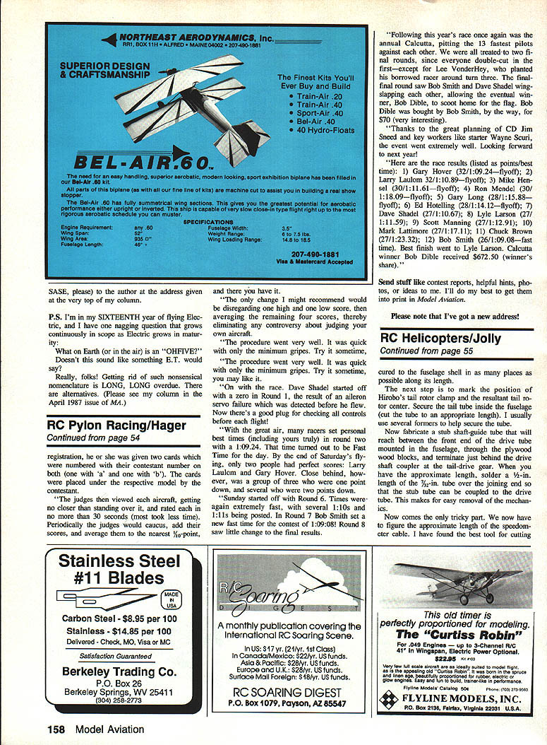
Welcome back. Two months ago I described the large-scale UH-1s I flew for the movie Die Hard. As promised, here is a description of the inexpensive tail drive used on those models.
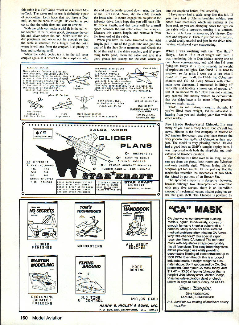
If you've given thought to flying scale helicopters you've undoubtedly found that many full-size ships have high-mounted tail rotors. That presents a problem: how to drive a high-mounted model tail rotor without leaving ugly, nonscale parts exposed. The solution I used is simple and proven — a speedometer cable running inside a curved brass tube. It's an old trick (Dieter Hegi's Cobra used it), but it works well.
Advantages over a solid shaft and bevel gearbox:
- Inexpensive
- Noncritical alignment
- Fewer setscrews to loosen
- Easy access for repair
- Lightweight and unobtrusive
Materials
- 36 in. length of K&S brass tube, 3/16 in. outside diameter
- Two 12 in. lengths of brass tube: one 3/16 in. OD and one 5/32 in. OD
- Package of replacement speedometer cable (auto-parts store)
- Stay-Brite silver solder
- Two 1/4 in. plywood rectangles (for GMP-style machines)
- Tools: drill (size matched to cable OD), hacksaw with fine blade or small cutoff wheel, pliers, soldering equipment
Tail-drive construction — step by step
- Remove the couplers from the tail drive shaft at both the tail-rotor gearbox and the main drive (loosen setscrews and twist couplers off with pliers).
- Measure the outside diameter of the speedometer cable. Using an appropriate drill, bore out the holes in the couplers so the cable sheath fits with a slight, loose interference fit. The inner core should be able to project slightly into the coupler.
- For GMP-style machines (other makes are similar): make two 1/4 in. plywood rectangles to fit between the wood bearers a few inches behind the main frames. Mount the tail-rotor gearbox a few inches behind the main frames.
- Determine how much of the 36 in. brass tube you will need. Bend the tube gradually — avoid kinks. Ideally the tube runs from a few inches behind the main frames to within an inch of the tail-rotor gearbox. Secure the tube along its length.
- Fabricate a stub shaft-guide tube that reaches from the front end of the drive tube (mounted in the fuselage), through the plywood bulkheads, and terminates just behind the drive-shaft coupler at the tail-rotor gearbox. When you have the approximate length, solder a 5/32 in. tube over the joining end so the stub tube can be coupled to the main drive tube. This allows easy removal of the mechanics.
- Cut the speedometer cable to length. The best cutting tools are a hacksaw with a fine blade or a small cutoff wheel. Cut carefully so you do not nick the inner core. After cutting, remove about 1/8 to 1/4 in. of the outer sheath from each end.
- Slide the cable into the bored coupler holes. The inner core should project slightly into the coupler; secure it by tightening the setscrew or with a small dab of solder where appropriate. Do not allow the inner core to bind in the drive tube — the run must be free and smooth.
- With the cable assembled and coupled at both ends, install the tail-rotor gearbox and couple the cable to it. Trial-fit the tail tube, formers, and clamps, then check coupler alignment. Make adjustments so the cable runs straight with only gradual bends.
- Secure the outer sheath to the tail tube in several places to prevent movement and chafing.
- Install the tail rotor and check tracking and pitch. Run the drive at low speed and listen for rough spots or binding. If everything runs smoothly, tighten all clamps and fasteners, recheck alignment, and finish the model.
I hope this inexpensive tail-drive arrangement helps those building high-tail-rotor scale ships. I'll report on the commercial Scale Helicopters tail-drives I ordered as soon as they arrive.
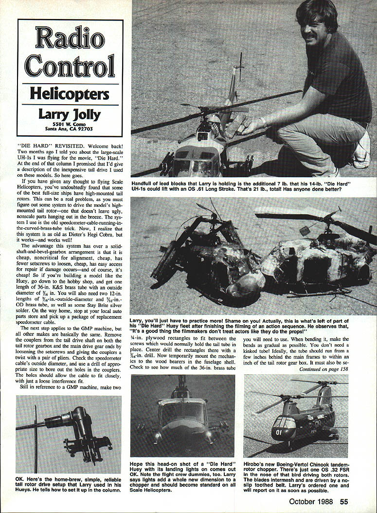
While working with the Die Hard Hueys I had to lift a lot of weight to simulate explosives and lights. With Cobra mechanisms, OS .61 Long Strokes, and 63 in. main rotors, I managed a vertical lift-off and a steady hover out of ground effect at 21 lb. I'm not claiming records — just demonstrating that these ships have more lifting potential than many expect. If you've lifted more, I'd be interested to hear about it and to share your feat with readers.
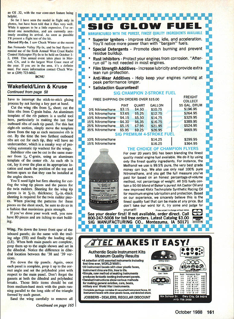
New Hirobo Boeing-Vertol Chinook
Hirobo is the first company to release an R/C tandem helicopter, choosing the Boeing-Vertol Chinook as the subject. The model is a little over 40 in. long. Both rotors are flybarless and only partially rigid. The mechanics look deceptively simple — like two Shuttles joined by portions of an Erector Set — but there is a great deal of mechanical output mixing under the shell. Two rotors are controlled with only five servos.
The Chinook is powered by an OS .32; the rear cone-start feature is helpful. I've seen photos and been told it flies very well. It appears a bit expensive, but I've ordered one and am anxiously awaiting its arrival. I will present a flight test of the kit as soon as possible.
Merced Fly-In
The Sixth Annual West Coast Radio Control Helicopter Fly-In will be held October 1–2, 1988, in Merced, CA. This is the largest West Coast meet of the year and is highly recommended if you're in the area. For more information contact Chuck Winter at (209) 723-6662.
BCNU
Transcribed from original scans by AI. Minor OCR errors may remain.

