
RADIO CONTROL HELICOPTERS
Paul Tradelius, 6704 Santiago, Ft. Worth, TX 76133
One of the more interesting helicopter projects I'm working on is as a member of the Massachusetts Institute of Technology (MIT) Unmanned Aerovehicle Team. When MIT approached me a couple of years ago, it wanted to develop a guidance system for a vehicle that will hover, go into forward flight, and perform aerobatic maneuvers. A model helicopter fit the requirements: it is readily available, relatively inexpensive compared to larger vehicles, and spare parts are easy to obtain.
Although most of my work has been with .60-size helicopters, this article details experiments to improve electric helicopter flight to meet MIT's requirements.
Collaboration and starting point
To begin a feasibility study, I talked with Ron Osinski, a member of the Pittsburgh Area Roto Runners (PARR). Ron and I have been club members for several years; he is regarded as the expert on Concept helicopters—from the Concept 30 to the Concept EP.
The Concept EP is designed as an electric helicopter, so getting it to hover and fly in forward flight is straightforward, but maximizing performance and aerobatics was the challenge. The experiments and this write-up are a direct result of Ron's untiring efforts, involving many hours of research and numerous ground and flight tests.
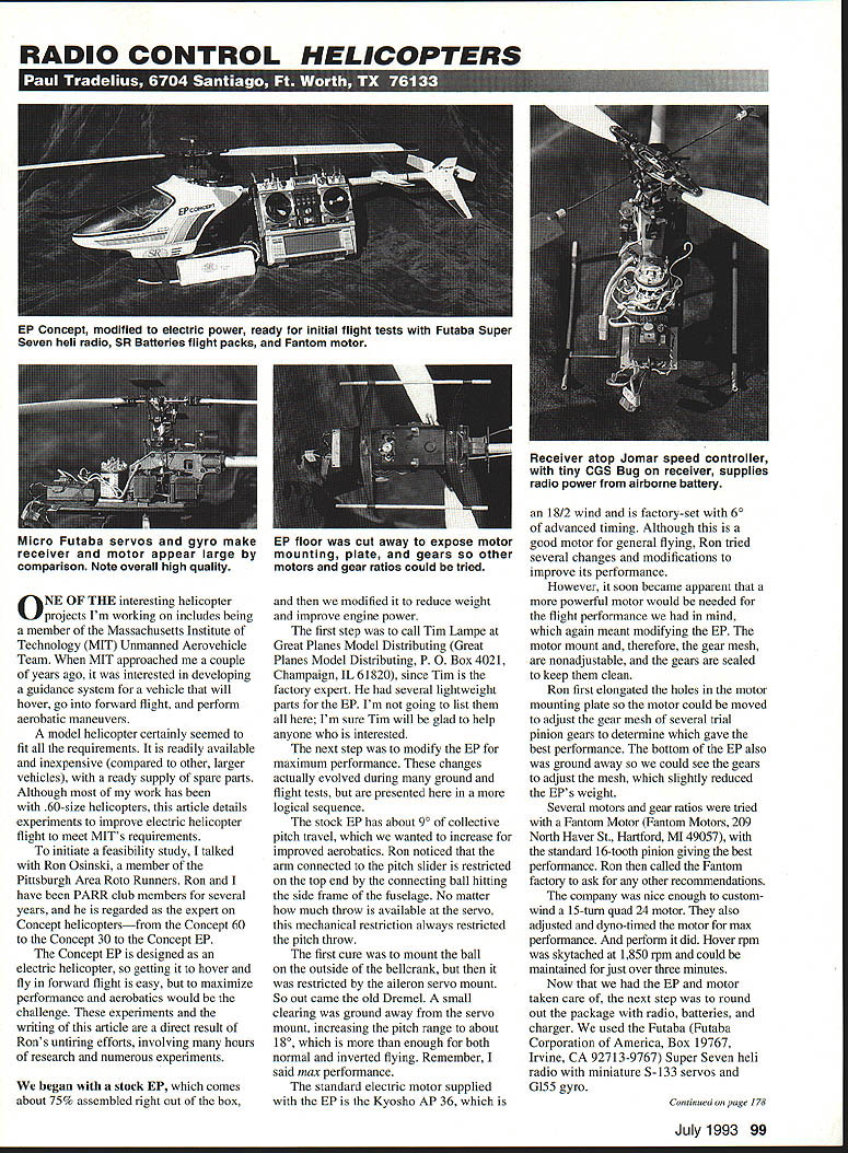
We began with a stock EP, which arrives about 75% assembled out of the box, and then modified it to reduce weight and improve power and control.
Factory parts and lightweight options
The first step was to call Tim Lampe at Great Planes Model Distributing (Great Planes Model Distributing, P.O. Box 4021, Champaign, IL 61820). Tim is the factory expert and had several lightweight parts for the EP. I won't list them all here, but Tim will be glad to help anyone interested.
Increasing collective pitch travel
The stock EP has about 9° of collective pitch travel, which we wanted to increase for better aerobatics. Ron noticed that the arm connected to the pitch slider was mechanically restricted on the top end: the connecting ball hit the side frame of the fuselage, limiting the pitch travel regardless of servo throw.
- First cure: mount the ball on the outside of the bellcrank. This solved the frame interference but then the ball hit the aileron servo mount.
- Next: grind a small clearance in the servo mount (Dremel work), increasing the pitch range to about 18°, which is more than enough for both normal and inverted flying.
Remember: these changes were made for maximum performance.
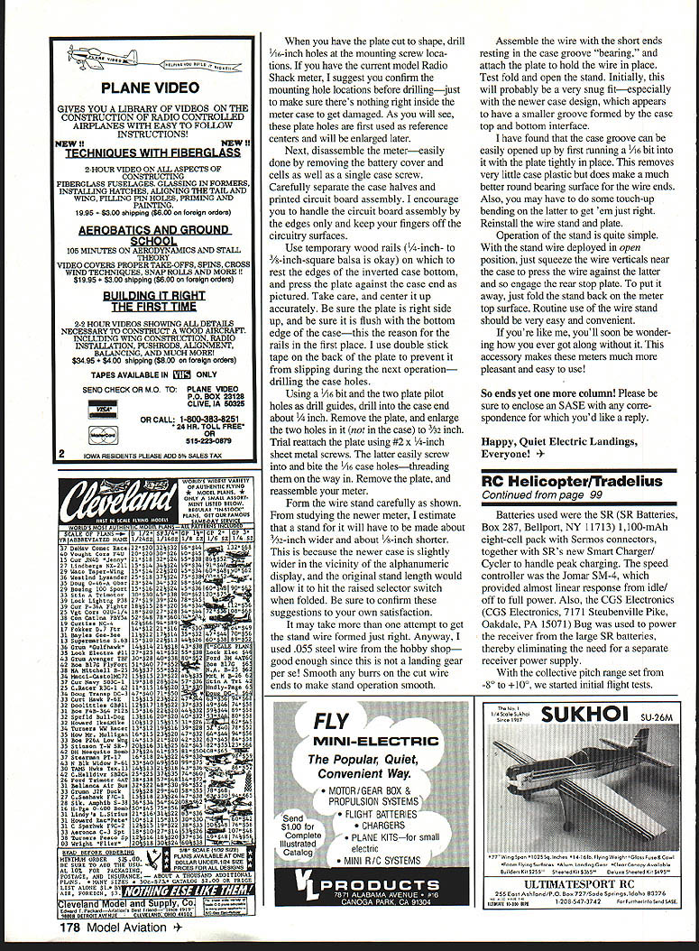
Motor modifications and gearing
The standard motor supplied with the EP is the Kyosho AP 36 (18/2 wind), factory-set with 6° of advanced timing. While this motor is good for general flying, Ron experimented to improve performance.
- The stock motor mount was nonadjustable and the gears were sealed. Ron elongated the holes in the motor mounting plate so the motor could be moved to adjust gear mesh.
- Several trial pinion gears were used to find the best performance. The bottom of the EP was ground away so we could see the gears and fine-tune the mesh, which also slightly reduced weight.
- Ron tested several motors and gear ratios with a Fantom motor. The standard 16-tooth pinion gave the best performance.
- Fantom Motors (Fantom Motors, 209 North Haver St., Hartford, MI 49057) custom-wound a 15-turn quad 24 motor for us and dyno-timed the motor for maximum performance. Hover rpm was measured at 1,850 rpm and could be maintained for just over three minutes.
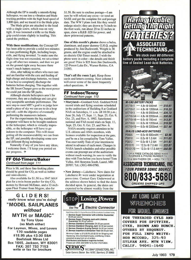
Radio, batteries, and charger
We rounded out the package with radio, batteries, and charger:
- Radio: Futaba Super Seven helicopter radio (Futaba Corporation of America, Box 19767, Irvine, CA 92713-9767)
- Servos: miniature S-133 servos
- Gyro: G155 gyro
- Charger: SR Smart Charger and SR battery packs
After discussing battery care with experienced hobbyists, we found it worked best to completely discharge the batteries before charging. This practice, together with the SR Smart Charger, gave the most usable power from the SR packs.
Vibration and blade tracking
Although the EP is usually a smooth-flying helicopter, we encountered vibration and blade-tracking problems at the high head speed of 1,800 rpm. The source was the blade grips.
The blade grips are attached to the head with a single screw and had been tightened very firmly. Loosening the screw slightly allowed the blade grip to rotate a bit in lead/lag, curing the vibration and tracking problem.
Flight results
With these modifications, the Concept EP provided a solid two minutes of maximum-performance flight, including loops, rolls, and inverted flying. To avoid overrunning the battery, we set a timer for two minutes and landed immediately, since battery reserve was minimal.
Electric helicopters aren't for everyone, but they present a rewarding challenge and can give acceptable aerobatic performance. Our next step toward MIT's goal is to determine how small a volume of air we can use to perform a loop and a roll, with the eventual objective of performing the maneuvers indoors.
For future experiments, either the mainframe computer will have to be brought outdoors to the helicopter—which is virtually impossible—or the helicopter will have to be flown indoors to the computer. That will require maximizing maneuverability from the EP and possibly developing new flying techniques. If you have ideas, I welcome them. I'll keep you posted on our progress.
Happy, Quiet Electric Landings, Everyone!
Please enclose an SASE with any correspondence for which you'd like a reply.
RADIO SHACK METER WIRE STAND MODIFICATION
This section describes adapting a folding wire stand to a Radio Shack multimeter case (instructions apply to older and newer models—verify fit for your meter).
Preparation and drilling
- Cut and shape the mounting plate to size.
- Drill 1/16-inch pilot holes in the plate at the mounting screw locations. If you have the current model Radio Shack meter, confirm hole locations before drilling the case—avoid damaging anything inside the case.
- Disassemble the meter by removing the battery cover, cells, and the single case screw. Carefully separate the case halves and the printed circuit board assembly. Handle the circuit board by the edges only.
Positioning the plate and drilling the case
- Use temporary wood rails (1/4- to 3/8-inch square balsa is fine) to support the inverted case bottom by its edges.
- Press the plate against the case, centered and flush with the bottom edge of the case. Use double-stick tape on the back of the plate to prevent slipping.
- Using a 1/16-inch bit and the two plate pilot holes as guides, drill into the case end about 1/4 inch.
- Remove the plate and enlarge the two holes in it (not in the case) to 3/32-inch.
- Trial-attach the plate using #2 x 1/4-inch sheet metal screws. These will bite into the 1/16-inch case holes and thread as they are inserted.
- Remove the plate and reassemble the meter.
Forming and installing the wire stand
- Form the stand wire from .055-inch steel wire. Note: for newer meter cases, the stand may need to be about 3/32-inch wider and about 1/8-inch shorter because of slight differences in the case around the alphanumeric display. Confirm fit before finalizing the wire.
- Smooth any burrs on the cut wire ends for smooth operation.
- Assemble the wire with the short ends resting in the case groove "bearing" and attach the plate to hold the wire in place.
- Test fold and open the stand. The fit may be snug, especially on newer case designs that have a smaller groove.
Adjusting the case groove and final fit
- If the groove is too tight, open it slightly by running a 1/16-inch bit into it with the plate tightly in place. This removes very little plastic but improves the bearing surface for the wire ends.
- Do any touch-up bending on the wire to achieve proper movement.
- Reinstall the wire stand and plate.
Operation
- To deploy the stand: with it open, squeeze the wire verticals near the case to press the wire against the case and engage the rear stop plate.
- To stow the stand: fold it back onto the meter top surface.
Routine use should be convenient and easy. Many users find they soon wonder how they ever got along without the stand.
Transcribed from original scans by AI. Minor OCR errors may remain.

