
RADIO CONTROL HELICOPTERS
Paul Tradelius, 6704 Santiago, Ft. Worth, TX 76133
Introduction
It wasn't too long ago when we were all happy with the new breed of helicopter radios that let us set more than one pitch curve. This capability is important to helicopter fliers because the collective pitch range needed for hovering and normal forward flight is not what is best for aerobatics. Different aerobatic maneuvers are better when flown with their own pitch curves.
The radios I'm referring to had a bunch of knobs under a protective cover, usually in the back of the radio. This enabled the user to adjust the high and low end points of a particular pitch curve, and the radio made a straight-line change between those set points. However, these radios had some serious drawbacks that the more modern computer radios have attempted to fix.
Older radios: drawbacks
First, the end points of the pitch curve were a little difficult to set because there was no readout of the pot position. A pitch gauge was mounted on the rotor blade, and small changes to one of the pots were made until a desired reading was obtained. It was not really that difficult, but there was no way to tell what the settings were simply by looking at the radio, and changes at the field were rather hit-and-miss as the pots were "tweaked" to improve helicopter performance.
Second, the pitch curve was not really a curve at all, but rather the setting of the end points with a straight-line change in between. I'm not sure why it was ever called a curve, except that the hovering pitch knob did make a change on the hover pitch, and therefore a curve was made.
Computer radios and digital pitch curves
The point of all this is to talk about our new computer radios, point out some of their features, and see how they make the helicopter setup so much easier than it was in the past. Considering the Futaba Super Seven helicopter radio as an example, one finds that it offers the standard normal pitch curve plus additional aerobatic curves for Idle Up 1 and 2, and another for throttle hold. And these curves are really curves, not just end-point adjustments. Three points on the curve can be independently adjusted, as can the two end points. This is a total of five points that can be adjusted for the pitch curve of your choice.
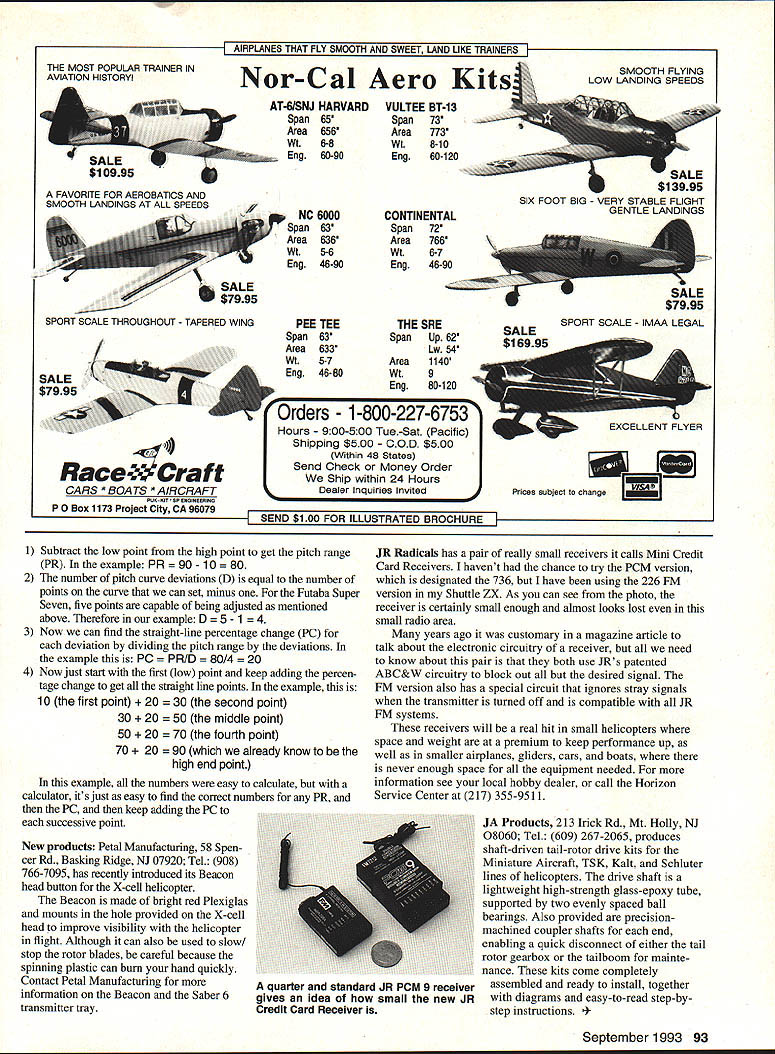
Another useful feature of this radio is that the pitch curve is displayed as a digital readout of servo-throw percentage. That is, the factory default curve is shown with digital percent values for the 0, 25, 50, 75, and 100% positions.
If this standard pitch curve were drawn (as in Figure 1, line A), it represents a straight line. However, the shape of the curve can be changed simply by modifying the digital values of the curve. Line B shows the same curve with the values changed to 0, 35, 60, 85, and 100.
Although altering the shape of the pitch curve will change (and, chances are, improve) the flying characteristics of your helicopter, it's important first to make sure we are starting with a straight line, and make changes from there. On the surface this sounds easy enough, since the factory settings mentioned above yield a straight line. But the problem develops when we don't want to start with the end points of 0 and 100%.
Calculating a straight-line pitch curve for custom end points
Suppose we put a pitch gauge on our rotor blade and determine that the low-end angle of attack we want is obtained at 10%, and the high end point is at 90%. Leaving the three other points at their factory settings of 25, 50, and 75% would cause the pitch curve to look uneven (line C).
The problem becomes: how can we adjust the end points to the values we need, and then set the other points along the curve to the correct settings to give us a straight-line curve as a starting point? An easy way to do this is with simple mathematics and an inexpensive electronic calculator. Use the following steps once the high and low end points are determined — in this case we will use the 10% and 90% points.
- Subtract the low point from the high point to get the pitch range (PR).
Example: PR = 90 − 10 = 80.
- The number of pitch curve deviations (D) equals the number of points on the curve minus 1.
Example: five adjustable points → D = 5 − 1 = 4.
- Find the straight-line percentage change (PC) by dividing the pitch range by deviations.
Example: PC = PR ÷ D = 80 ÷ 4 = 20.
- Start at the low point and keep adding the percentage change to get the straight-line points.
Example: 10 (first point), 30 (second), 50 (middle), 70 (fourth), 90 (fifth).
In this example all the numbers were easy to calculate, but with a calculator it's just as easy to find the correct numbers for any PR, then the PC, and then keep adding the PC to each successive point.
New products
- Petal Manufacturing, 58 Spencer Rd., Basking Ridge, NJ 07920; Tel.: (908) 766-7095.
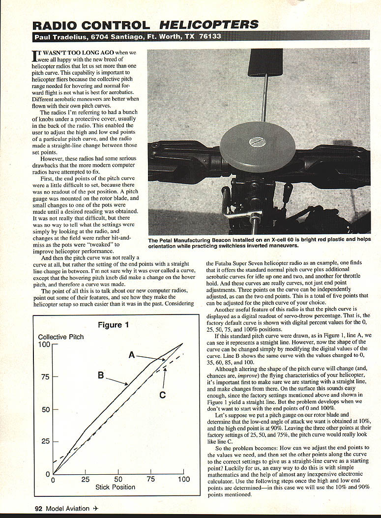
Petal has introduced its Beacon head button for the X-cell helicopter. The Beacon is made of bright red Plexiglas and mounts in the hole provided on the X-cell head to improve visibility of the helicopter in flight. Although it can also be used to slow/stop the rotor blades, be careful — the spinning plastic can burn your hand quickly. Contact Petal Manufacturing for more information on the Beacon and the Sabre 6 transmitter tray.
- JR Radicals: a pair of very small receivers called Mini Credit Card Receivers.
I haven't had the chance to try the PCM version (designated the 736), but I have been using the 226 FM version in my Shuttle ZX. As you can see from the photo, the receiver is certainly small enough and almost looks lost even in the small radio area. Both models use JR's patented ABC&W circuitry to block out all but the desired signal. The FM version also has a special circuit that ignores stray signals when the transmitter is turned off and is compatible with all JR FM systems. These receivers will be a real hit in small helicopters (where space and weight are at a premium) as well as in smaller airplanes, gliders, cars, and boats. For more information see your local hobby dealer, or call the Horizon Service Center at (217) 355-9511.
- JA Products, 213 Irick Rd., Mt. Holly, NJ 08060; Tel.: (609) 267-2065.
JA Products produces shaft-driven tail-rotor drive kits for the Miniature Aircraft, TSK, Kalt, and Schleuter lines of helicopters. The drive shaft is a lightweight, high-strength glass-epoxy tube supported by two evenly spaced ball bearings. Also provided are precision-machined coupler shafts for each end, enabling a quick disconnect of either the tail-rotor gearbox or the tailboom for maintenance. These kits come completely assembled and ready to install, together with diagrams and easy-to-read step-by-step instructions.
Transcribed from original scans by AI. Minor OCR errors may remain.

