
RADIO CONTROL: HELICOPTERS
Paul Tradelius
6704 Santiago, Ft. Worth, TX 76133
Editor's note
In the September issue, a reference was made to JR's new Credit Card Receivers. The correct model number is 236, not 736, and of course, the company name is JR Radios. Apologies for the errors.
Collective-pitch setup and techniques
The last couple of issues I have been talking about collective pitch—how to get a straight-line "curve" (in the September issue), and use of the pitch gauge (in the October issue). To round out this series on collective pitch, here are some of my techniques for getting the initial pitch setup on a helicopter, and some mistakes I see others make.
The first question I ask myself is what type of flying I intend to do with this particular helicopter. If I'm setting up a helicopter for a novice, I would like a greatly reduced pitch range, something on the order of 0° to +6°. This will desensitize the collective control, help keep descents from being too violent, and also reduce the climbing capability. If you can hover at six inches, you can also hover six feet—but the six-inch level is much safer. This would also be the only pitch curve needed until the flying skills are mastered to advance into forward flight.
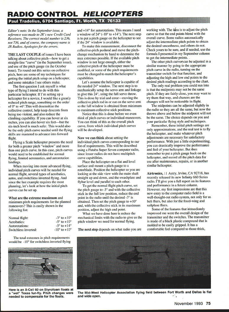
Flying a scale helicopter presents the need for both a greater pitch "window" and more than one pitch curve. In this case, pitch curves would need to be established for normal flying, limited aerobatics, and autorotation landings.
When moving into more advanced flying, individual pitch curves will be needed for normal flight, several types of aerobatics, autos, and switchless inverted flying. And since the last example requires the most planning, let's look at how the initial pitch curves can be set up.
Determine pitch extremes
What are the extreme maximum and minimum pitch requirements for the planned maneuvers? This is easily shown in the following list:
- Normal flight: -3° to +10°
- Aerobatics: -5° to +10°
- Autorotations: -5° to +14°
- Switchless inverted: -10° to +10°
The total extremes in pitch requirements would be -10° for switchless inverted flying and +14° for autorotations. This means I need a window of 24° (-10° to +14°). The next step is to put a pitch gauge on the helicopter to see if the 24° window is available.
To make this measurement, disconnect the collective-pitch pushrod and move the pitch-change mechanism by hand to determine the maximum extremes possible. If the available pitch window is not large enough, either the collective pitch of the helicopter must be modified, or some of the pitch requirements must be changed to match the helicopter's capabilities.
Let's assume the helicopter is capable of the needed 24° window. The next step is to mechanically set up the servo arm and linkage to give this 24° using the full servo throw. This is done by trial and error—moving the collective pitch rod in or out on the servo arm so the full window is obtained from minimum to maximum collective stick positions.
Notice that this is done before we even think of pitch curves or individual maneuvers. You can think of this as the overall pitch curve, from which individual pitch curves will be developed.
Setting individual pitch curves (computing radios)
Now we can think about setting the individual pitch curves corresponding to our list of requirements. This will be described using a Futaba Super Seven computer radio, since lesser radios do not have multipitch curve capability.
Place the helicopter on a flat and level surface and mount a pitch gauge to a rotor blade. Position the helicopter so you are looking at the side view with the main shaft straight up and down, and the swashplate and flybar level and parallel to each other.
To get the normal flight pitch curve, set the pitch gauge to -3° and, with the collective stick in the full low position, reduce the end point in the radio until the desired -3° is obtained. Then set the pitch gauge to +10° and, with the collective stick in its maximum position, adjust the high end point.
What we have done here is reduce the mechanical limits with the radio to give us the pitch window we need for normal flying.
The next step depends on what radio you are working with. The idea is to adjust the pitch curve so that the end points blend with the overall curve. Some radios automatically adjust the intermediate points to obtain the desired smoothness, and others do not. Check yours to be sure, and if needed, use the formula I presented in my September column to get the intermediate points.
The other pitch curves can be adjusted in a similar manner by going to the appropriate pitch curve in the radio, turning on the transmitter switch function, and adjusting the high and low end points to the desired pitch readings according to the chart.
The only real problem you could run into is that the midpoints may not be the same pitch. If they are fairly close, you may want to try them that way, and chances are the changes will not be noticeable in flight.
The midpoints can be adjusted slightly in the radio so they are all the same, but now the throws above and below the midpoint will not be the same. The choice depends on you and your particular flying style and techniques.
Remember, these initial pitch settings are only approximations, and the real test is to fly the helicopter and make whatever pitch adjustments are necessary for satisfactory performance. With just a little experimenting, you can drastically improve the performance and feel of your helicopter. But then remember to put a pitch gauge back on the helicopter, and record all the pitch data for future use after maintenance, repairs, or in another similar helicopter.
New radios and servos
Airtronics, 11 Autry, Irvine, CA 92718, has recently released its new Infinity 660 Series radio. I'll give you a full report on its features and performance in a later column. However, my first impressions are that this new entry to the computer radio field is a well-thought-out radio system, not only for our helifliers, but also for the fixed-wing and sailplane flyers.
Some of the features that immediately impressed me were the overall design of the transmitter and the switches. The transmitter is made of a black plastic compound that is molded to be easily gripped. It has a comfortable feel compared to those thick, boxy transmitters that are hard to hold.
Some of the standard toggle switches have been replaced with rocker switches, which again are molded to the finger for easy activation. But what is really great is that these switches are assignable. Now you can place the idle-up, throttle-hold, etc., exactly where you want it, and even control the direction of the switch to activate that function.
There is certainly more to this electronic powerhouse from Airtronics than can be described in a few short paragraphs, but after flying it for a while, I’ll give you a whole column on its performance.
Hitec R/C, 10729 Wheatlands Ave., Suite C, Santee, CA 92071, has released its HS-605BB Ultra Torque Servo, which I am installing in a separate helicopter for testing. This servo will work with any popular radio, and has specs that are almost too good to be true. With a standard 4.8-volt airborne pack, it claims an output of 77 inch-ounces of torque at a speed of only 0.16 seconds, with even better numbers on a six-volt pack.
It also incorporates dual ball bearings and is the only servo I know of that uses helical gears. These helical gears are not only useful in managing all that power, but also for improving the precision and centering of the overall servo. Together with their well-known RCD receivers, these servos should make an excellent flight pack for those new radios that allow several models to be flown from one radio.
Happy, quiet power landings, everyone.
Transcribed from original scans by AI. Minor OCR errors may remain.

