
RADIO CONTROL HELICOPTERS
Paul Tradelius, 6704 Santiago, Ft. Worth TX 76133
PITCH CURVES
In a previous issue I talked about some of the special features a helicopter radio has compared to an airplane radio. However, when you purchase a helicopter radio, it will still take an understanding of the various functions to make everything come together in a suitable program that will make your helicopter fly the way you want.
One of the critical helicopter parameters is the pitch curve—how the collective pitch follows the movements of the throttle/collective (T/C) stick. Several years ago helicopter radios only gave us the ability to adjust the endpoints of the collective pitch range, which were connected by a straight line (as opposed to a curve).
With the advent of the computer radio, we have the ability to adjust the shape of the curve between the endpoints to vary the collective-pitch output in relation to the control-stick input.
Although pitch curves may sound intimidating, if you take them one step at a time they are quite easy to understand and apply. They provide a new level of control to helicopter flight. There is no single right or wrong way to adjust a pitch curve — it is strictly a matter of technique. It's up to your individual taste, and what works best for you and your helicopter.
The following is the technique I use. It's logical and simplifies the process in an easy-to-understand, step-by-step approach.
INITIAL PARAMETERS
Some less-expensive radios may only provide adjustments for one pitch range. More advanced radios provide several flight modes, each with its own pitch curve, as well as other adjustable parameters. This is why I recommend that you get the best equipment you can comfortably afford — you will quickly outgrow a lower-performance radio.
Keeping your radio limitations in mind, determine what maneuvers you would like to perform with the available collective-pitch ranges.
Assume that you have the three basic flight modes: normal, idle-up, and throttle-hold. (Your radio may have more flight modes; these three will suffice for our discussion.)
Let's say that the normal mode will be used just for hovering. You're not interested in rapid climbs or descents — just a good hovering platform that is not very sensitive on the collective inputs.
The idle-up mode will be used for general flight and limited aerobatics. Throttle-hold mode will be used for autorotation.
To get the performance you are looking for, you have to match the correct pitch curve to each of these three flight modes. As a starting point, consider the following collective-pitch ranges for initial setup, noting the required pitch window (range):
- Normal: -1° to +7° = 8° window
- Idle-up: -3° to +9° = 12° window
- Throttle-hold: -4° to +12° = 16° window
Of these initial collective-pitch estimates, the biggest window needed is 16° for autorotation. Your next step is to verify that your helicopter can provide the 16° window.
MECHANICAL SETUP
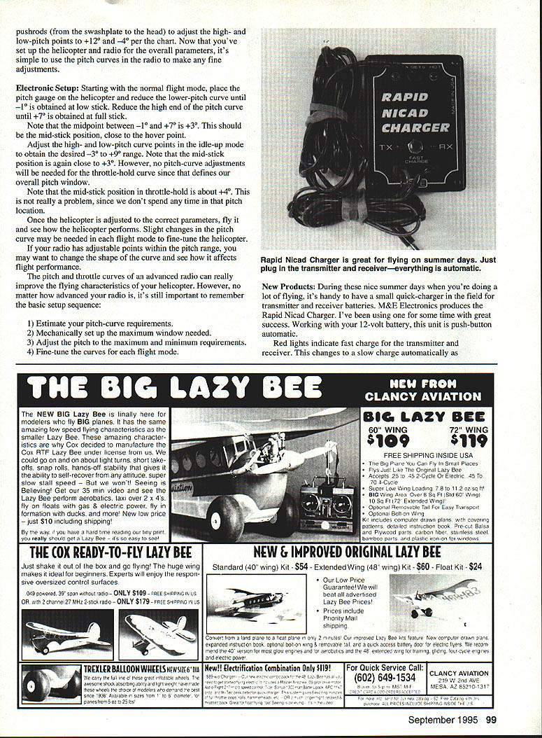
In the following discussion on pitch windows, I'm not concerned with the actual pitch readings, just the pitch windows they provide. Adjusting the exact collective-pitch numbers will be accomplished later.
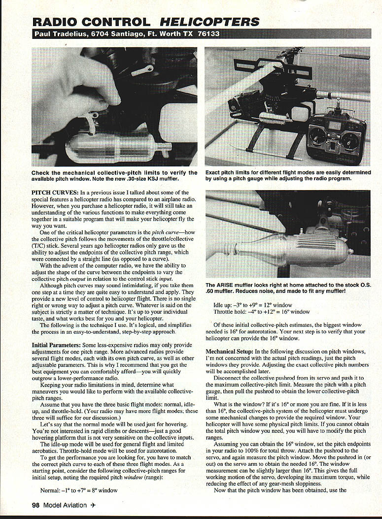
- Disconnect the collective pushrod from its servo and push it to the maximum collective-pitch limit. Measure the maximum collective-pitch limit with a pitch gauge.
- Pull the pushrod to obtain the lower collective-pitch limit and measure it.
What is the window? If it's 16° or more you are fine. If it is less than 16°, the collective-pitch system of the helicopter must undergo some mechanical changes to provide the required window. Your helicopter will have some physical pitch limits. If you cannot obtain the total pitch window you need, you will have to modify the pitch ranges.
Assuming you can obtain the 16° window, set the pitch endpoints in your radio to 100% for total throw. Attach the pushrod to the servo and again measure the pitch window. Move the pushrod in (or out) on the servo arm to obtain the needed 16°. The window measurement can be slightly larger than 16°. This gives the full working motion of the servo, developing its maximum torque, while reducing the effect of any gear-mesh sloppiness.
ELECTRONIC SETUP
Starting in the normal flight mode, place the pitch gauge on the helicopter and adjust the low-end pitch-curve point until about -1° is obtained at low stick. Adjust the high-end pitch-curve point until about +7° is obtained at full stick.
Note that the midpoint between -1° and +7° is +3°. This should be the mid-stick position, close to the hover point.
Adjust the high- and low-pitch curve points in the idle-up mode to obtain the desired -3° to +9° range. The midpoint of that range is again about +3°, so mid-stick remains near the hover point.
No pitch-curve adjustments will be needed for the throttle-hold curve since that defines our overall pitch window. The mid-stick position in throttle-hold may be about +4°; this is not really a problem because we don't spend time at that pitch location during normal flight.
Now that you've set up the helicopter radio overall parameters, fly the helicopter and see how it performs. Slight changes in the pitch curve may be needed in each flight mode to fine-tune the helicopter. If your radio has adjustable points within the pitch range, you may want to change the shape of the curve and see how it affects flight performance. The pitch and throttle curves of an advanced radio can greatly improve the flying characteristics of your helicopter.
Basic setup sequence:
- Estimate your pitch-curve requirements.
- Mechanically set up the maximum window needed.
- Adjust the pitch to the maximum and minimum requirements.
- Fine-tune the curves for each flight mode.
Transcribed from original scans by AI. Minor OCR errors may remain.

