
Radio Control: Helicopters
Paul Tradelius 6704 Santiago, Ft. Worth TX 76133
Servo Control Effectiveness
Those of you who have been in the radio-control hobby for many years will remember the early proportional servos—the ones with linear push-pull output. At that time it was thought linear output was desirable because it more closely matched the transmitter stick position, but the mechanics involved made the servo large and heavy. These linear-output servos were only available for a few years, until the radio manufacturers settled on the rotary-output servos we now have.
Aside from the history lesson, the real point is that linear servo output is more desirable than the rotary output we now use—a fact recognized many years ago. The question then becomes: what is wrong with rotary-output servos? We have used them for years with great success. The answer is that nothing is fundamentally wrong with rotary output, except that the servo loses effectiveness as the arm (or wheel) rotates away from the center position.
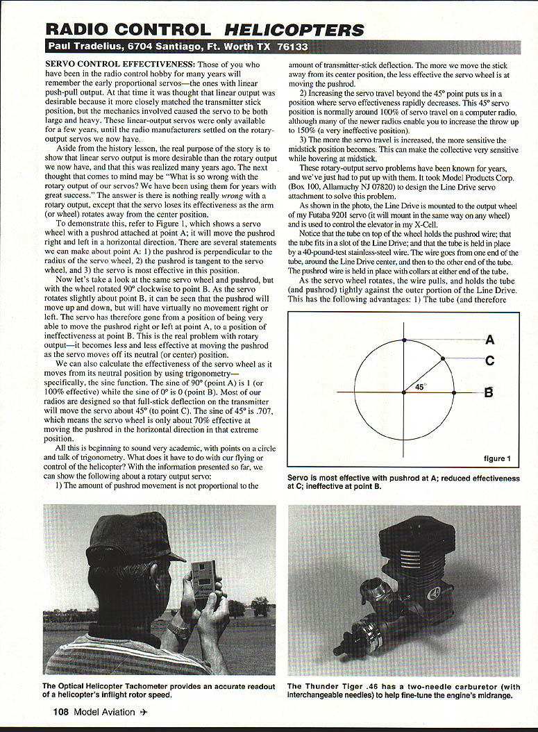
To demonstrate this, refer to Figure 1, which shows a servo wheel with a pushrod attached at point A; it will move the pushrod right and left in a horizontal direction. Several statements can be made about point A:
- The pushrod is perpendicular to the radius of the servo wheel.
- The pushrod is tangent to the servo wheel.
- The servo is most effective in this position.
Now look at the same servo wheel and pushrod with the wheel rotated 90° clockwise to point B. As the servo rotates slightly about point B, the pushrod will move up and down but will have virtually no movement right or left. The servo has therefore gone from a position of being very effective at moving the pushrod right or left (point A) to a position of ineffectiveness (point B). This is the real problem with rotary output—the ability to move the pushrod decreases as the servo moves off its neutral (center) position.
We can also calculate servo effectiveness as it moves from neutral using trigonometry—specifically the sine function. The sine of 90° (point A) is 1 (100% effective), while the sine of 0° (point B) is 0. Most radios are designed so that full-stick deflection on the transmitter moves the servo about 45° (to point C). The sine of 45° is 0.707, which means the servo wheel is only about 70% effective at moving the pushrod horizontally in that extreme position.
What does this mean for flying and helicopter control? From the above we can show the following about a rotary-output servo:
- The amount of pushrod movement is not proportional to transmitter-stick deflection. The farther the stick is moved from center, the less effective the servo wheel is at moving the pushrod.
- Increasing servo travel beyond the 45° point rapidly decreases servo effectiveness. This 45° position is normally around 100% of servo travel on a computer radio, although many newer radios enable you to increase throw up to 150% (a very ineffective position).
- The more servo travel is increased, the more sensitive the midstick position becomes. This can make the collective very sensitive while hovering at midstick.
These rotary-output servo issues have been known for years, and we have just had to accept them. Model Products Corp. (Box 100, Allamuchy, NJ 07820) designed the Line Drive servo attachment to address this problem.
Line Drive Servo Attachment
The Line Drive mounts to the output wheel of a servo (shown mounted on my Futaba 9201, but it will mount the same way on any wheel) and is used to control the elevator in my X-Cell.
The tube on top of the wheel holds the pushrod wire; the tube fits in a slot on the Line Drive and is held in place by a 40-pound-test stainless-steel wire. The wire runs from one end of the tube, around the Line Drive center, and to the other end of the tube. The pushrod wire is secured with collars at either end of the tube.
As the servo wheel rotates, the wire pulls and holds the tube (and pushrod) tightly against the outer portion of the Line Drive. This provides the following advantages:
- The tube keeps the pushrod tangent to the drive, so the servo remains effective throughout its travel (reducing the reduced effectiveness at C and the ineffectiveness at B).
- Control sensitivity is therefore the same throughout the transmitter stick/servo range.
- Friction caused by the cable is very low.
- Zero backlash.
I am using Line Drives on the elevator and collective in my X-Cell Custom right now. Although I don't see an earth-shaking improvement, I notice distinct benefits: the elevator has a softer neutral and improved hovering while retaining full swashplate throw for aerobatics. The collective is almost completely linear compared to the collective stick movement because the pushrod is kept tangent and effective throughout the servo travel. Full throw has been especially noticeable during autorotations: the Line Drive has improved servo throw at the extreme position—this does not provide more collective for touchdown, but it gives a more positive input.
New Products
Advanced Aero Fueler
22nd Century Aero Products (2763 West Ave. L, Suite 295, Lancaster CA 93536) produces the new Advanced Aero Fueler for use with glow fuel or gasoline. Until the Aero Fueler, fueling (and defueling) helicopters or airplanes received little standardized thought. Most of us developed our own methods for keeping fuel fresh week to week and preventing spills in the car.
The Advanced Aero Fueler solves these problems. I have used it for several months and the issues associated with fuel storage and handling have gone away. The Aero Fueler features an airtight fuel-cap system, color-coded locking quick-disconnects, and high-quality coiled fuel tubing. These features help keep your fuel fresh as long as you want. The system mounts easily to any fuel bottle or can. It won't help in an autorotation emergency, but it will make everyday flying more convenient and enjoyable.
Optical Heli Tachometer
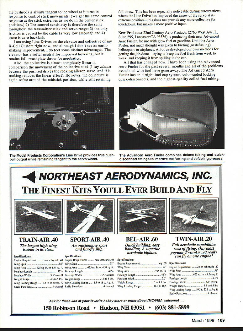
The Optical Heli Tachometer by Miniature Aircraft (3743 Silver Star Rd., Orlando FL 32808) is a small, easy-to-use handheld electronic tachometer that measures a helicopter's rotor speed in flight.
If you can see the rotorblades (hovering or during a maneuver), you can accurately determine rotor speed. Look at the helicopter through the viewfinder and press the toggle switch until the rotor blades appear stationary. The rotor speed will appear on the digital readout.
Slower rotor speeds are more suitable for hovering—now the novice or FAI flier can make accurate rotor-speed changes to suit wind conditions. For those who want to maximize performance, the Optical Heli Tachometer helps evaluate how much rotor speed is really needed. A high rotor speed is desirable for aerobatics, but beyond a point small increases do not improve performance and can overheat the engine with a lean run. The tachometer helps match rotor speed to overall in-flight helicopter performance.
Thunder Tiger 46 Engine
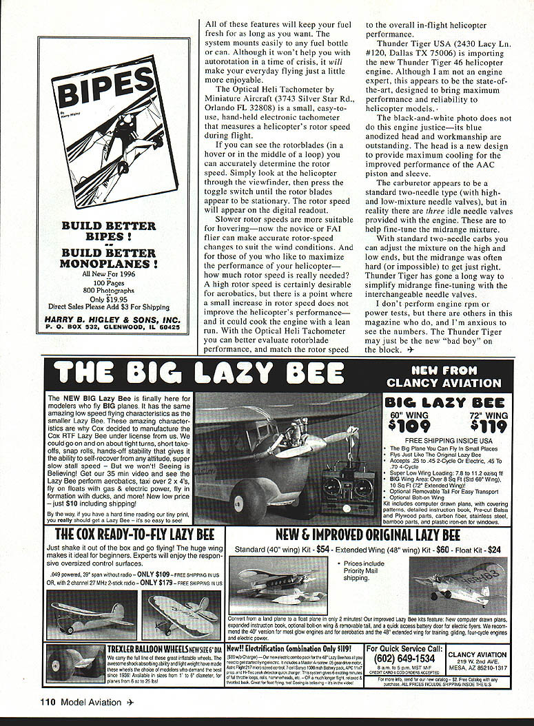
Thunder Tiger USA (2430 Lacy Ln. #120, Dallas TX 75006) is importing the new Thunder Tiger 46 helicopter engine. Although I am not an engine expert, this appears to be state-of-the-art, designed for maximum performance and reliability in helicopter models.
The black-and-white photo does not do the engine justice—its blue-anodized head and workmanship are outstanding. The head is a new design to provide maximum cooling for improved performance of the AAC piston and sleeve.
The carburetor appears to be a standard two-needle type (with high- and low-mixture needle valves), but in fact there are three idle needle valves provided with the engine to help fine-tune the midrange mixture. With standard two-needle carbs you can adjust the mixture on the high and low ends, but the midrange was often hard (or impossible) to get just right. Thunder Tiger has gone a long way to simplify midrange fine-tuning with the interchangeable needle valves.
I don't perform engine rpm or power tests, but others in this magazine do, and I'm anxious to see the numbers. The Thunder Tiger may just be the new "bad boy" on the block.
Transcribed from original scans by AI. Minor OCR errors may remain.

