
Radio Control: Helicopters
□ Walt Schoonard
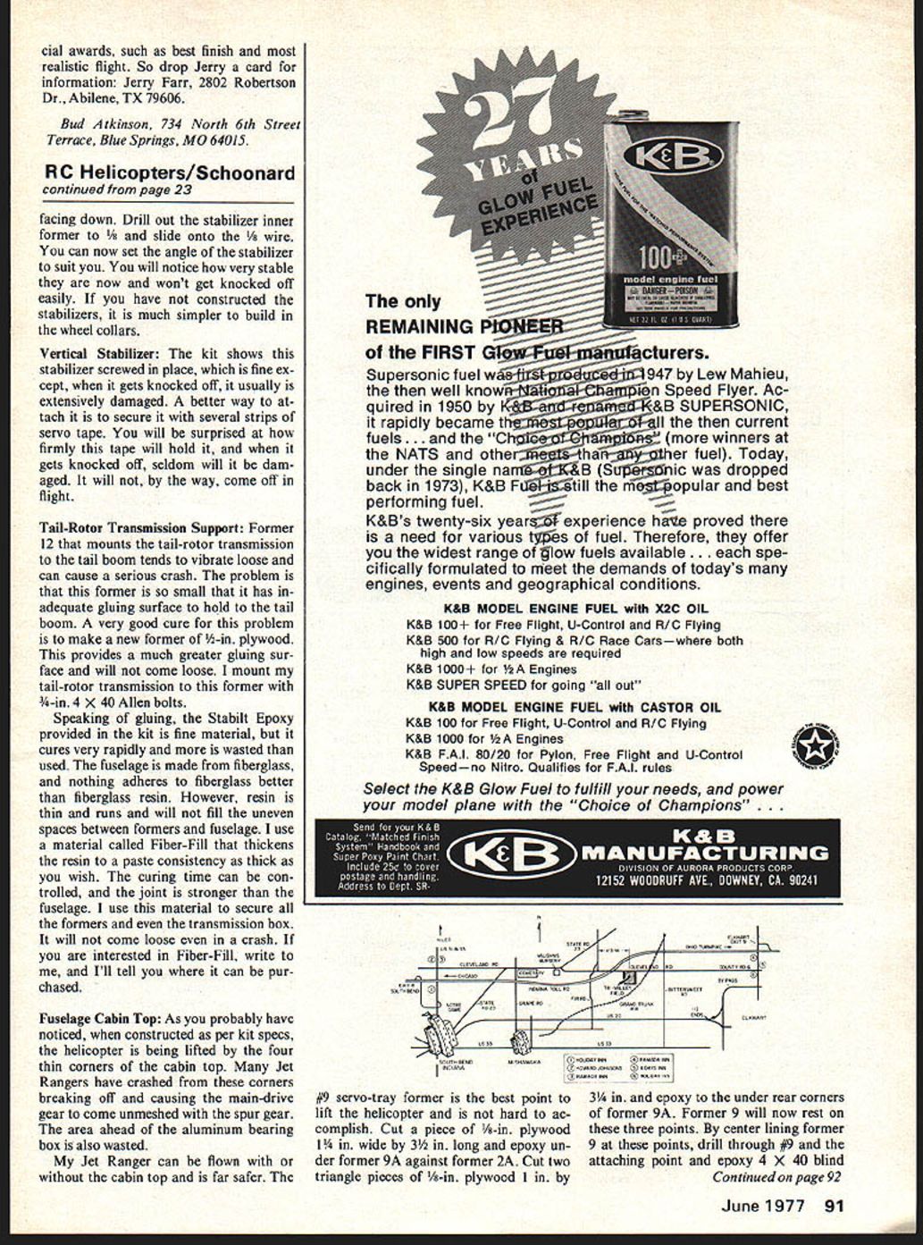
EVEN THOUGH the helicopter rules have been voted in and will be in the 1978-79 Rule Book printing, the event itself will not be part of the regular Nationals until later. Because of this and the fact that a large portion of RC helicopter activity is in the eastern part of the country, it has been decided to hold the 1977 Helicopter Nationals in South Bend, Indiana, on June 10, 11 and 12. They will be held for those three days at the Tri-Valley RC field, 14154 Cleveland Road, South Bend, Indiana. The events will be Novice, Intermediate, Expert, and Scale with awards through three places plus Best Scratch-Built helicopter. The reason for adding the third day is that we are expecting a large entry, and it will permit us to run it at a more leisurely pace. It also will give more time for the contestants to get their act together. The South Bend area has plenty of major motels and good restaurants.
For reservations call: Holiday Inn South Bend—219-272-6600, Howard Johnsons South—219-272-1500, Ramada Inn South Bend—219-272-5220, Ramada Inn Elkhart—219-262-1581, 8 Days Inn Elkhart—219-262-3541, Holiday Inn Elkhart—219-264-7502.
I will need judges so if you would like to judge, write or call me, and I will send you all the material to study. I also need sponsors to help cover the expense of this meet. If you wish to help in any way, please contact Walt Schoonard, 2080 Sharon Road, Winter Park, Florida 32789—phone (305) 647-1335 evenings.
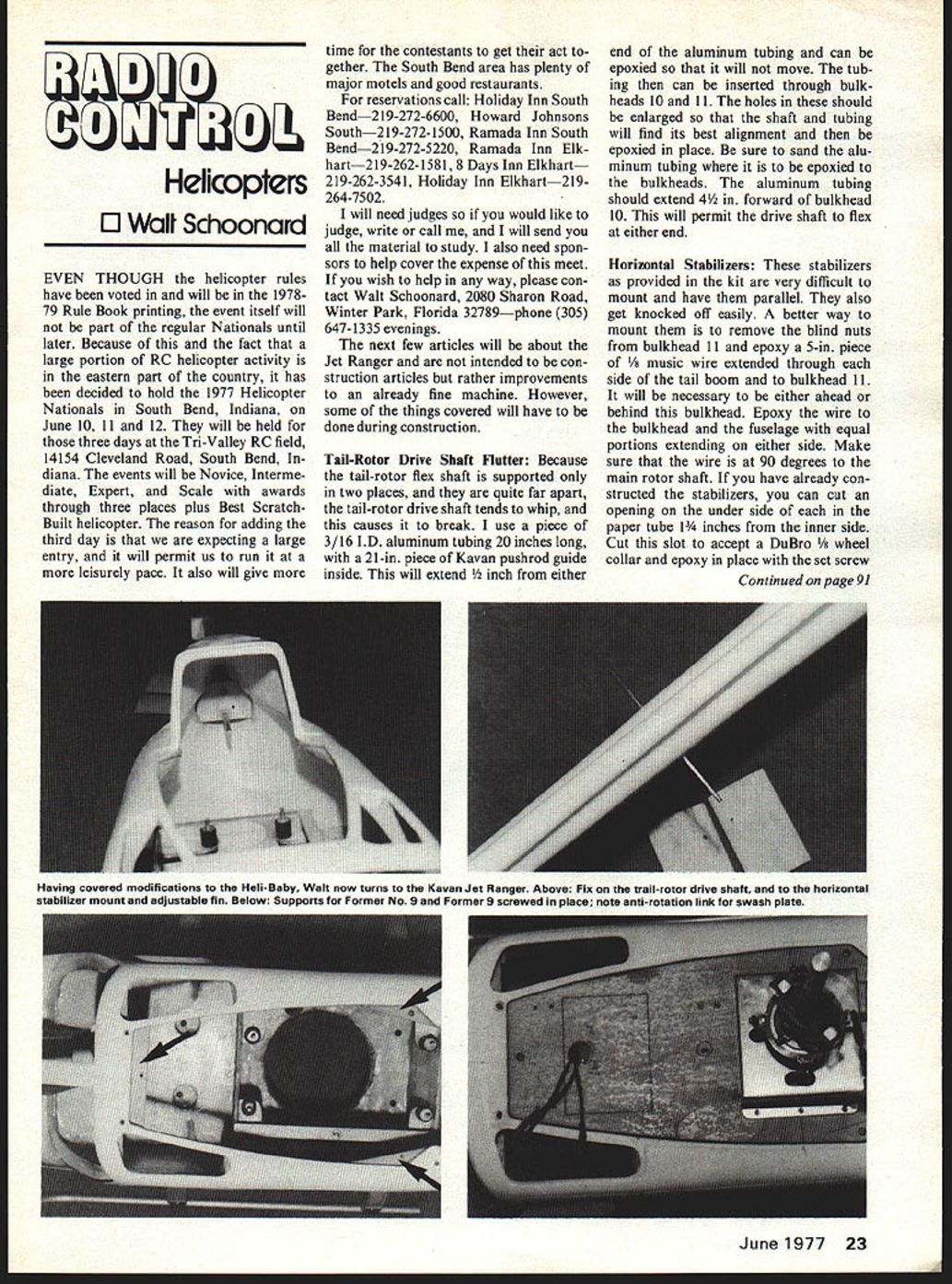
The next few articles will be about the Jet Ranger and are not intended to be construction articles but rather improvements to an already fine machine. However, some of the things covered will have to be done during construction.
Tail-Rotor Drive Shaft Flutter: Because the tail-rotor flex shaft is supported only in two places, and they are quite far apart, the tail-rotor drive shaft tends to whip, and this causes it to break. I use a piece of 3/16 I.D. aluminum tubing 20 inches long, with a 21-in. piece of Kavan pushrod guide inside. This will extend 1/2 inch from either end of the aluminum tubing and can be epoxied so that it will not move. The tubing then can be inserted through bulkheads 10 and 11. The holes in these should be enlarged so that the shaft and tubing will find its best alignment and then be epoxied in place. Be sure to sand the aluminum tubing where it is to be epoxied to the bulkheads. The aluminum tubing should extend 4 1/2 in. forward of bulkhead 10. This will permit the drive shaft to flex at either end.
Horizontal Stabilizers: These stabilizers as provided in the kit are very difficult to mount and have them parallel. They also get knocked off easily. A better way to mount them is to remove the blind nuts from bulkhead 11 and epoxy a 5-in. piece of 1/8 music wire extended through each side of the tail boom and to bulkhead 11. It will be necessary to be either ahead or behind this bulkhead. Epoxy the wire to the bulkhead and the fuselage with equal portions extending on either side. Make sure that the wire is at 90 degrees to the main rotor shaft. If you have already constructed the stabilizers, you can cut an opening on the under side of each in the paper tube 1 3/4 inches from the inner side. Cut this slot to accept a DuBro 1/8 wheel collar and epoxy in place with the set screw. Facing down. Drill out the stabilizer inner former to 1/8 and slide onto the 1/8 wire. You can now set the angle of the stabilizer to suit you. You will notice how very stable they are now and won't get knocked off easily. If you have not constructed the stabilizers, it is much simpler to build in the wheel collars.
Vertical Stabilizer:
The kit shows this stabilizer screwed in place, which is fine except, when it gets knocked off, it usually is extensively damaged. A better way to attach it is to secure it with several strips of servo tape. You will be surprised at how firmly this tape will hold it, and when it gets knocked off, seldom will it be damaged. It will not, by the way, come off in flight.
Tail-Rotor Transmission Support:
Former 12 that mounts the tail-rotor transmission to the tail boom tends to vibrate loose and can cause a serious crash. The problem is that this former is so small that it has inadequate gluing surface to hold to the tail boom. A very good cure for this problem is to make a new former of 1/4-in. plywood. This provides a much greater gluing surface and will not come loose. I mount my tail-rotor transmission to this former with 3/16-in. 4 X 40 Allen bolts.
Speaking of gluing, the Stabilit Epoxy provided in the kit is fine material, but it cures very rapidly and more is wasted than used. The fuselage is made from fiberglass, and nothing adheres to fiberglass better than fiberglass resin. However, resin is thin and runs and will not fill the uneven spaces between formers and fuselage. I use a material called Fiber-Fill that thickens the resin to a paste consistency as thick as you wish. The curing time can be controlled, and the joint is stronger than the fuselage. I use this material to secure all the formers and even the transmission box. It will not come loose even in a crash. If you are interested in Fiber-Fill, write to me, and I'll tell you where it can be purchased.
Fuselage Cabin Top:
As you probably have noticed, when constructed as per kit specs, the helicopter is being lifted by the four thin corners of the cabin top. Many Jet Rangers have crashed from these corners breaking off and causing the main-drive gear to come unmeshed with the spur gear. The area ahead of the aluminum bearing box is also wasted.
My Jet Ranger can be flown with or without the cabin top and is far safer. The #9 servo-tray former is the best point to lift the helicopter and is not hard to accomplish. Cut a piece of 1/8-in. plywood 1 1/4 in. wide by 3 1/2 in. long and epoxy under former 9A against former 2A. Cut two triangle pieces of 1/8-in. plywood 1 in. by 3/4 in. and epoxy to the under rear corners of former 9A. Former 9 will now rest on these three points. By center lining former 9 at these points, drill through 9A and the attaching point and epoxy 4 X 40 blind nuts and secure with 4 X 40 Allen bolts. Now place cabin top in place and secure in normal manner. The cabin top can now be removed without disturbing the former 9 to make any needed adjustments. The radio receiver can be mounted in the area ahead of the aluminum bearing box, which eliminates the need for servo extensions.
Next month's column will cover the external needle-valve extension, glow-plug connectors, landing-gear improvements, and head modifications.
I have had a complaint about the way that I end my column. It is not intended to be a smart remark but rather a word of encouragement. I have yet to see a person fail to learn to fly when they put their mind to it. So as a word of encouragement, I say, "If you're not flying, it's because you are not trying hard enough."
Walt Schoonard, 2080 Sharon Rd., Winter Park, FL 32789.
Transcribed from original scans by AI. Minor OCR errors may remain.

