
Radio Control: Helicopters
Walt Schoonard
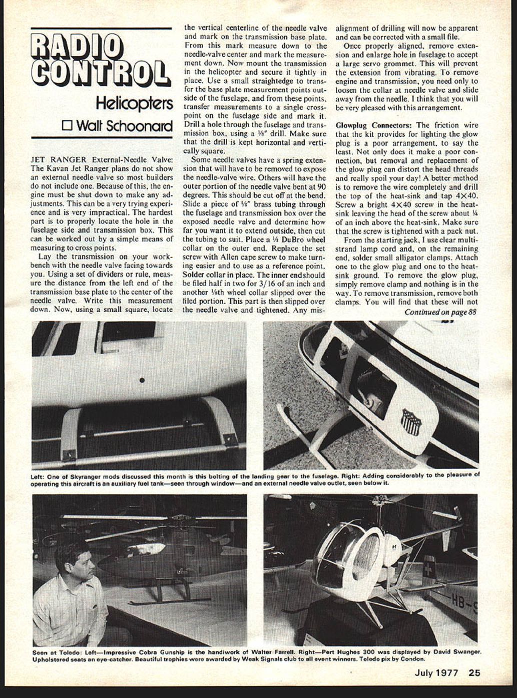
JET RANGER External-Needle Valve: The Kavan Jet Ranger plans do not show an external needle valve so most builders do not include one. Because of this, the engine must be shut down to make any adjustments. This can be a very trying experience and is very impractical. The hardest part is to properly locate the hole in the fuselage side and transmission box. This can be worked out by a simple means of measuring to cross points.
Lay the transmission on your workbench with the needle valve facing towards you. Using a set of dividers or rule, measure the distance from the left end of the transmission base plate to the center of the needle valve. Write this measurement down. Now, using a small square, locate the vertical centerline of the needle valve and mark on the transmission base plate. From this mark measure down to the needle-valve center and mark the measurement down. Now mount the transmission in the helicopter and secure it tightly in place. Use a small straightedge to transfer the base plate measurement points outside of the fuselage, and from these points, transfer measurements to a single cross-point on the fuselage side and mark it. Drill a hole through the fuselage and transmission box, using a 1/8" drill. Make sure that the drill is kept horizontal and vertically square.
Some needle valves have a spring extension that will have to be removed to expose the needle-valve wire. Others will have the outer portion of the needle valve bent at 90 degrees. This should be cut off at the bend. Slide a piece of 1/8" brass tubing through the fuselage and transmission box over the exposed needle valve and determine how far you want it to extend outside, then cut the tubing to suit. Place a 1/8" DuBro wheel collar on the outer end. Replace the set screw with an Allen cap screw to make turning easier and to use as a reference point. Solder collar in place. The inner end should be filed half in two for 3/16 of an inch and another 1/8" wheel collar slipped over the filed portion. This part is then slipped over the needle valve and tightened. Any misalignment of drilling will now be apparent and can be corrected with a small file.
Once properly aligned, remove extension and enlarge hole in fuselage to accept a large servo grommet. This will prevent the extension from vibrating. To remove engine and transmission, you need only to loosen the collar at the needle valve and slide away from the needle. I think that you will be very pleased with this arrangement.
Glowplug Connectors: The friction wire that the kit provides for lighting the glow plug is a poor arrangement, to say the least. Not only does it make a poor connection, but removal and replacement of the glow plug can distort the head threads and really spoil your day! A better method is to remove the wire completely and drill the top of the heat-sink and tap 4-40. Screw a bright 4-40 screw in the heat-sink leaving the head of the screw about 1/4" above the heat-sink. Make sure that the screw is tightened with a pack nut. From the starting jack, I use clear multistrand lamp cord and, on the remaining end, solder small alligator clamps. Attach one to the glow plug and one to the heat-sink ground. To remove the glow plug, simply remove clamp and nothing is in the way. To remove transmission, remove both clamps. You will find that these will not come off in flight and will make for better starting because of the better connections.
Fuel Tank Auxiliary Feed: The Jet Ranger plans show the fuel tank crosswise of the fuselage. This is fine except, when in tight left-hand turns, the fuel can run away from the pickup, and suddenly the engine goes dead with disastrous results. A flying buddy of mine, Norm Holland, worked out a very good auxiliary tank arrangement. He uses a regular 16- or 18-ounce tank in standard location and a 2-ounce slant nylon tank silicone glued to the transmission box left side. Note picture.
The plumbing sounds complicated, but it isn't if you follow these directions. Each tank needs a pickup tube and an overflow tube. Run a line from the muffler-pressure tap to the overflow tube on the large tank. The large tank-pickup tube should be connected to the overflow tube of the small tank. Make sure that the overflow tube in the small tank is bent so that it will go up into the most upper corner of the tank so that it will fill completely. The pickup tube in the small tank should go to a filter and then to the engine. To fill, the line to the engine should be broken before the filter so that the small tank fills first, and the overflow then fills the large tank which vents into the muffler.
You can fill by breaking this line or run it through a Robart Fueler. I highly recommend the Robart Fueler; it prevents the engine from flooding while fueling and also permits turning the engine over with no fuel going to it. All this by just turning a switch!
With the auxiliary fuel tank, it is virtually impossible to get the helicopter in a position where it will starve for fuel, plus the added safety of 2 ounces more fuel capacity! Be sure to safety secure all plumbing connections by sliding a 1/8" sleeve of fuel tubing over the plumbing tubing at each joint.
Landing Gear Attachment: Probably the most unsightly and impractical thing on the Jet Ranger is the landing-gear shocks. They are impractical from the fact that on hard landing an unbelievable pressure is exerted on each joint where they attach to the fuselage and the cross struts. I have seen these shocks driven right through the bottom of the fuselage, plus breaking the landing struts from just a hard landing. A better way to attach the landing gear is to bolt it directly to the fuselage. This way there is at least 5 inches of each landing strut in contact with the fuselage, and it looks far better too.
Fuselage Cabin Top: In last month's column, I left out one of the most important parts of attaching the #9 servo tray. What I left out was the center mounting. When the #9 servo tray is mounted front and rear, the lift pressure point is exerted just in front of the aluminum-bearing box. I use a 6 x 1/2" piece of 1/8" plywood that goes under #9 and extends under #9A on each side. It is secured on each side to #9 by a 4 x 40 screw that goes through #9 to a blind nut in the cross support. When the servo tray needs to be removed, this support can be slid out through the rear windows.
Tail Rotor Delta Hinge: The rigid hub that holds the tail-rotor blades and the lack of individual adjustments of the tail-rotor blades makes it almost impossible to perfectly track the tail-rotor blades. This causes vibration. Also, the rigidity of the tail-rotor disc causes the tail to bounce around in gusty winds. I have spent a great deal of time studying the Delta Hinge on the Proto-type Jet Ranger and have felt for a long time that this could be adapted to our models. Several hubs were worked up by hand and tried on the models. Several things immediately became apparent. Perfect blade tracking was instantly automatic. Vibration from not tracking disappeared, and the yawing action from gusty wind was greatly reduced. What actually takes place is that, instead of the wind gust moving the tail, it moved the tail-rotor disc, which automatically added pitch to the opposite blade, which instantly brought the disc back to normal (90 degrees to the tail-rotor shaft).
Because of the precision by which the hub must be hinged, it is practically impossible for the average modeler to build this hub so it has been made available from Miniature Aircraft Supply, 2563 Diversified Way, Orlando, FL 32807.
Next month's column will cover rigid mounting of the swashplate for smoother cyclic control and head modifications for super smooth flying. If I can get permission from the developer, that is. Don't forget the Helicopter Nationals, June 10, 11, 12 in South Bend, Indiana. If you're not flying, you're not trying hard enough!!
Walt Schoonard, 2080 Sharon Rd., Winter Park, FL 32789.
Transcribed from original scans by AI. Minor OCR errors may remain.

