
Radio Control: Helicopters
Walt Schoonard
I HAVE BEEN telling you that I would fill you in on Bill Youman's head mods as soon as he gave me permission. He has just given it to me a few days ago, and in the meantime, a similar mod was published in the September issue of Model Builder magazine. The odd thing about this is that Bill developed his mods from long hours of trial and error, and Mr. Kavan had done practically the same thing some time ago. I am totally convinced that Bill was working without any outside help or influence so I guess that the old saying "great minds work in the same paths" still holds true.
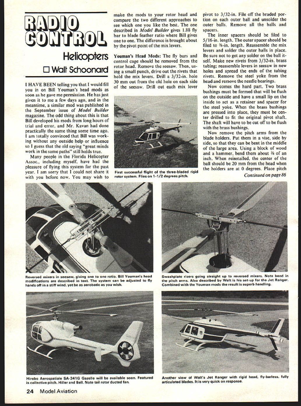
Many people in the Florida Helicopter Assoc., including myself, have had the pleasure of flying the system for the past year. I am sorry that I could not share it with you before now. You may wish to make the mods to your rotor head and compare the two different approaches to see which one you like the best. The one described in Model Builder gives 1.88 fly bar to blade feather ratio where Bill gives one to one. The difference is brought about by the pivot point of the mix levers.
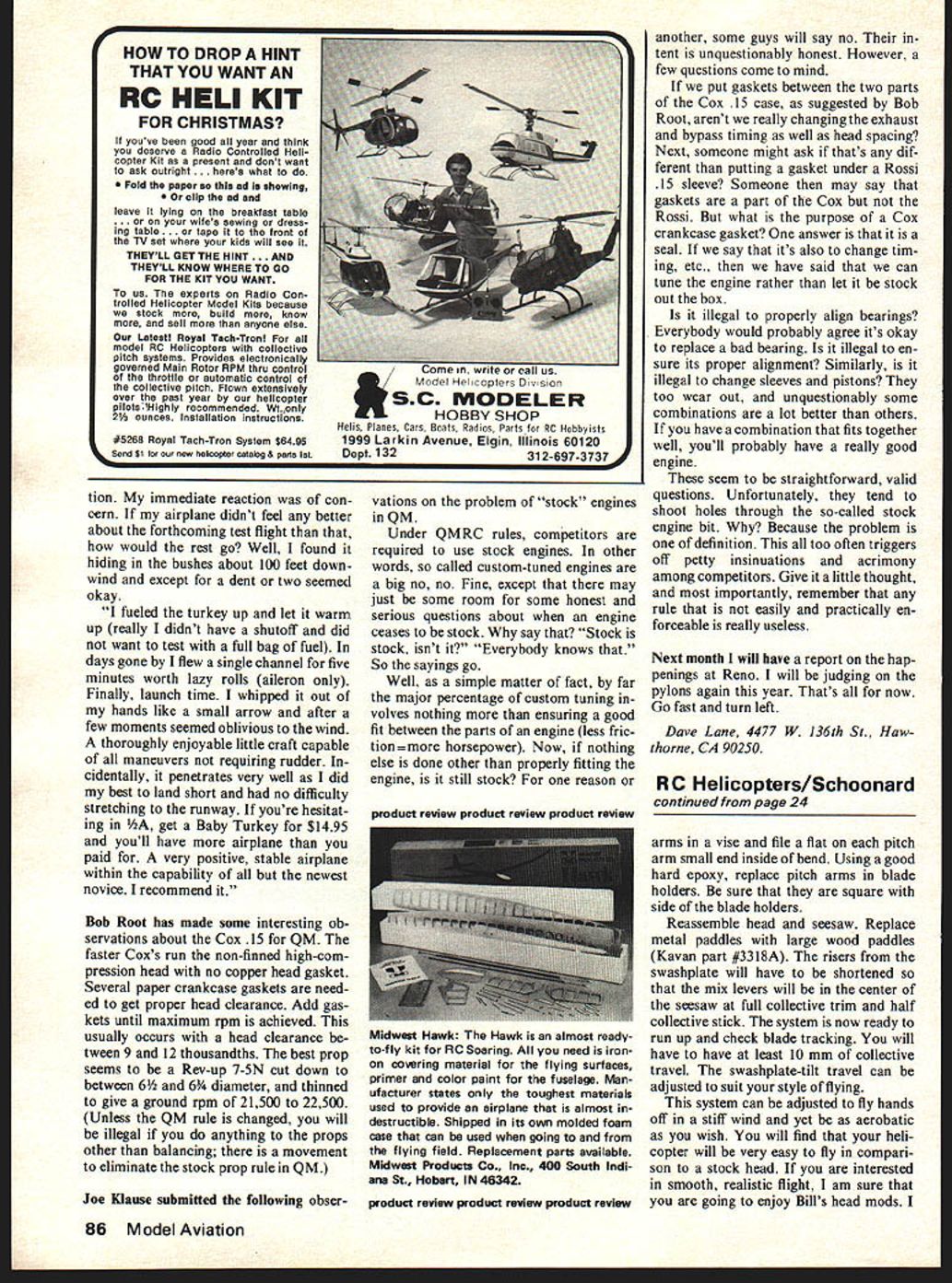
Youman's Head Mods: The fly bars and control cage should be removed from the rotor head. Remove the seesaw. Then, using a small punch, drive out the rivets that hold the mix levers. Drill a 3/32-in. hole 30 mm out from the old hole on each side of the seesaw. Drill out each mix lever pivot to 3/32-in. File off the brazed portion on each outer ball and unsolder the outer balls. Remove all the balls and spacers. The inner spacers should be filed to 5/16-in. length. The outer spacer should be filed to 5/8-in. length. Reassemble the mix levers and solder the outer balls in place. Be sure not to get any solder on the ball itself. Make new rivets from 3/32-in. brass tubing; reassemble levers in seesaw in new holes and spread the ends of the tubing rivets. Remove the steel yoke from the head and remove the needle bearings.
Now comes the hard part. Two brass bushings must be formed that will be flush on the outside and have a small lip on the inside to act as a retainer and spacer for the steel yoke. When the brass bushings are pressed into place, they must be center drilled to fit the original pivot shaft. The shaft will have to be cut off to be flush with the brass bushings.
Now remove the pitch arms from the blade holders. Put them in a vise, side by side, so that they can be bent in the middle of the large area. Using a block of wood and a hammer, bend them about 1/8-in. When reinstalled, the center of the ball should be 20 mm from the head when the holders are at 0 degrees. Place pitch holders at 0 degrees. Place pitch arms in a vise and file a flat on each pitch arm small end inside of bend. Using a good hard epoxy, replace pitch arms in blade holders. Be sure that they are square with side of the blade holders.
Reassemble head and seesaw. Replace metal paddles with large wood paddles (Kavan part #3318A). The risers from the swashplate will have to be shortened so that the mix levers will be in the center of the seesaw at full collective trim and half collective stick. The system is now ready to run up and check blade tracking. You will have to have at least 10 mm of collective travel. The swashplate-to-tail travel can be adjusted to suit your style of flying.
This system can be adjusted to fly hands off in a stiff wind and yet be as acrobatic as you wish. You will find that your helicopter will be very easy to fly in comparison to a stock head. If you are interested in smooth, realistic flight, I am sure that you are going to enjoy Bill's head mods. I have modified several heads as described in Model Builder, which is much easier to do and gives almost the same results. You will have to decide which is your cup of tea.
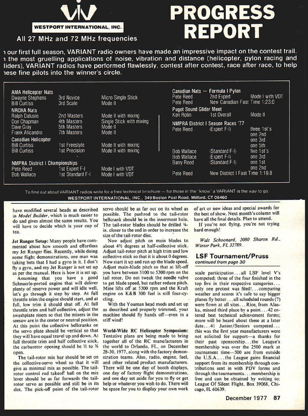
Jet Ranger Setup:
Many people have commented about how smooth and effortless my Jet Ranger flies. Recently, while doing some flight demonstrations, one man was taking bets that I had a gyro in it. I don't fly a gyro, and my Jet Ranger is not set up as per the manual. Here is how it is set up.
Assuming that you have a good Schnuerle-ported engine that will deliver plenty of reserve power and will idle well, let's go through it step by step. At full throttle trim the engine should start, and at full low trim it should shut off. At full throttle trim and half collective, adjust the swashplate risers so that the mixers in the seesaw are in the center or neutral position. At this point the collective bellcranks on the servo plate should be vertical so that they will have equal travel up and down. At full throttle trim and half collective stick, the carburetor opening should be 1/2 to 3/4 open.
The tail-rotor mix bar should be set on the collective-servo wheel so that it will give as minimal mix as possible. The tail-rotor control rod takeoff ball on the mix lever should be as far forwards toward the tail-rotor servo as possible and still be in its slot. The pick-off point of the tail-rotor servo should be as far out on its wheel as possible. The pushrod to the tail-rotor bellcrank should be in the innermost hole. The tail-rotor blades should be drilled 1/4-in. closer to the end in order to increase the size of the tail-rotor disc.
Now adjust pitch on main blades to about 4 1/2 degrees at half-collective stick. Adjust tail-rotor pitch at high trim and low collective stick so that it is about 0 degrees. Now start it up and run up the blade speed. Adjust main-blade pitch so that at lift-off you have between 5100 to 5300 rpm on the tail rotor. Do not tweak the needle valve to get blade speed, but rather reduce pitch. Mine lifts off at 5300 rpm and the Kraft engine on K & B 500 fuel is still four-cycling.
With the Youman head mods and set up as described and properly trimmed, your machine should fly hands off—even in a stiff wind!
World-Wide RC Helicopter Symposium:
Tentative plans are being made to bring together all of the RC manufacturers in the world to Orlando, FL, on December 28-30, 1977, along with the factory demonstration teams. Also, radio, engine, fuel, and other related product manufacturers. There will be one day of booth displays, one day of factory flight demonstrations, and one day set aside for you to fly or get help or whatever you wish to do. There will be space for you to display your own work of art or new ideas and special awards for best of show. Next month's column will have all the final details. Plan to attend.
Walt Schoonard, 2080 Sharon Rd., Winter Park, FL 32789.
Transcribed from original scans by AI. Minor OCR errors may remain.

