
Radio Control: Helicopters
Dave Chesney
Introduction
The Heliboys have been with us for almost two years and during that time they have proven their flying qualities by accumulating an impressive list of contest wins. From Novice to Expert, the Heliboy is capable of both mild and wild flying. Although emphasis has been on the aerobatic qualities, I believe aerobatic machines should be considered not only by experienced pilots but also by those with less experience. The responsiveness of the aerobatic machines does not necessarily offset stability; this is particularly true of the Heliboy.
The Heliboy kit
Overview
The Heliboy is a .60-powered, collective-pitch trainer helicopter that is capable of wild aerobatics right out of the box. The kit contains the parts necessary to fly the machine either with the Hiller rigid rotor system or with the "Beller" system used on the aerobatic machine. The Hiller system was probably intended for beginners, but after flying the aerobatic version I’m convinced a beginner could have equal success using the Beller mixers from the start.
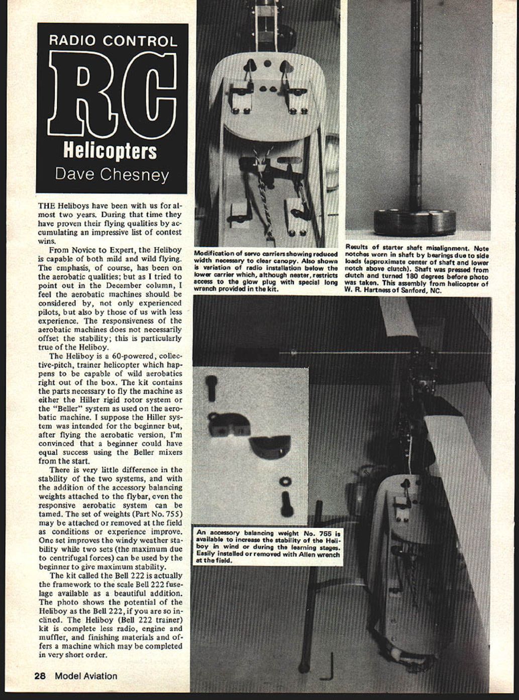
There is very little difference in the stability of the two systems. With the accessory balancing weights attached to the flybar (Part No. 755), even the responsive aerobatic system can be tamed. One set improves windy-weather stability; two sets (the maximum due to centrifugal forces) give maximum stability for the beginner. The weights may be attached or removed at the field as conditions or experience change.
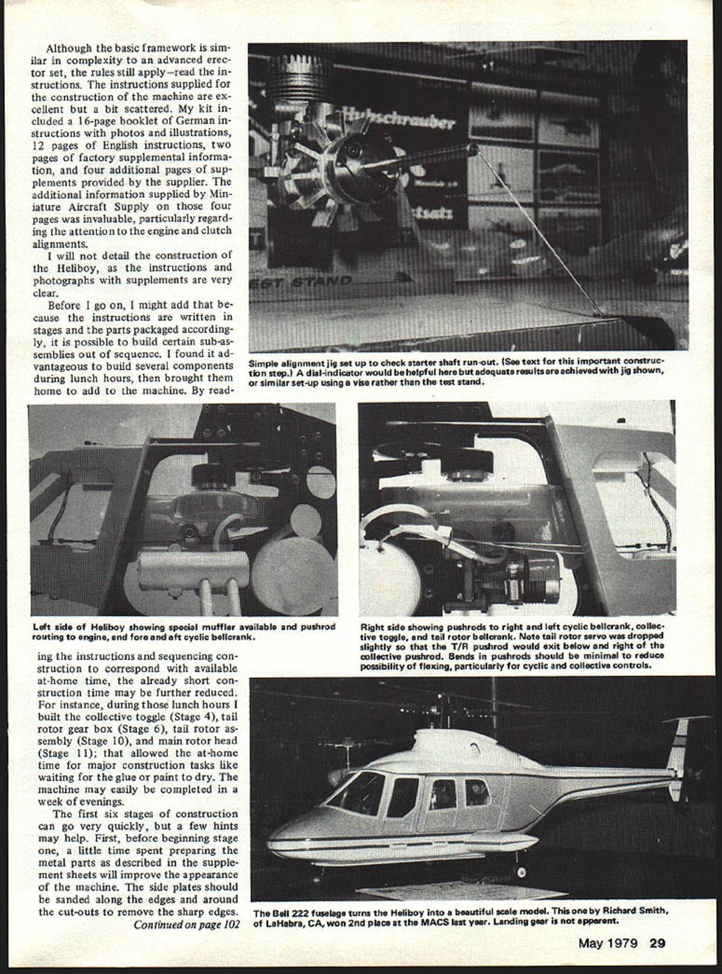
The kit sold as the Bell 222 is actually the framework for a scale Bell 222 fuselage available as an attractive optional addition. The Heliboy (Bell 222 trainer) kit is complete except for radio, engine and muffler, finishing materials, and offers a machine that can be completed in very short order.
Instructions and supplements
Although the basic framework is similar in complexity to an advanced erector set, the rules still apply—read the instructions. The supplied instructions are excellent but a bit scattered. My kit included:
- a 16-page booklet of German instructions with photos and illustrations,
- 12 pages of English instructions,
- two pages of factory supplemental information,
- four additional pages of supplements provided by the supplier.
The four-page supplement from Miniature Aircraft Supply (M.A.S.) was invaluable, particularly regarding engine and clutch alignments.
Construction tips
I will not detail the entire construction here, since the instructions and photographs with supplements are clear, but a few hints may speed the build and improve the finished appearance.
Sequencing work
The instructions are written in stages and parts are packaged accordingly, but it is possible to build subassemblies out of sequence. I found it advantageous to build several components during lunch hours and bring them home to add to the machine. Examples of small assemblies you can do in short periods:
- collective toggle (Stage 4),
- tail rotor gearbox (Stage 6),
- tail rotor assembly (Stage 10),
- main rotor head (Stage 11).
Sequencing construction to match available time can reduce the total build time; the machine may easily be completed in a week of evenings.
Metal parts and finishes
Before starting Stage 1, spend a little time preparing the metal parts:
- Sand the side plates along the edges and around cutouts to remove sharp edges.
- Polish or prepare for painting the side frames, skid struts, reinforcement profiles, skids, and tail boom using Mag Brite or Scotch-Brite (available at auto accessory stores).
I had my machine black anodized rather than painted, but I am told an anodized finish may cause radio problems due to insulating properties. With that in mind, I recommend polishing the metal rather than painting or anodizing, or assembling parts as they come from the box.
Specific fit and alignment checks
- Swash-plate ball No. 452: My upper bearing block was cut too deep and the inner race of the bearing sat below the outer edge of the block. Remove the block, remove the bearing, sand the top of the block slightly to the correct level, then reinstall. Tighten the set screw in the swash-plate ball securely to prevent the shaft from slipping downward.
- Stage 5: I found it easier to install the drive shaft (351) into the tail tube (350) before attaching the gear and bearing assembly. Grease the drive shaft lightly before assembly. Position the gear and bearing assembly between the side frames, then mate the tail tube and drive shaft and adjust per the instructions.
- Stage 6: Pack the bearings with grease, assemble sealed side out, and use Loctite on the gear set screws. Set gear backlash with a dollar bill, then fill the transmission case with grease and assemble per the instructions. Close the lower holes of the gear case with the provided screws but don’t screw them in too far.
- Before installing the tail fin and preassembled bearing block with T/R control assembly, remove the screw to the control arm and install two washers between the arm and the bearing block to provide additional clearance and avoid interference between the control arm and the underside of the transmission box. Reposition the control rod to avoid binding.
Tail skid reinforcement
The tail skid as provided is a little flimsy and may be made more rigid by bracing it with wire:
- Run a brace wire from the screw at the left front of the transmission to the bottom of the skid.
- Bend the brace wire to conform with the skid, wrap, and solder the joint.
This modification (published by Don Chapman in RCM’s Hover column) prevents the skid from flexing on tail-first landings and avoids the tail rotors touching the ground and chewing up the plastic drive gear. The main gear replacement was expensive, so investing a few cents in wire and solder is worthwhile.
Engine starting system and alignment
Perhaps the neatest feature of the Heliboy is the engine starting system. Using the starter extension available from Miniature Aircraft Supply (see Oct. ’78 MA) allows quick engine starts even with a partially flooded engine. The starter extension is available separately for $6.95 and fits Sullivan, Sonotronic and Kavan starters; part numbers are S1010, S01010, and K1011, respectively. The convenience of the direct-start system is well worth careful alignment of the starter shaft and clutch assembly.
Starter/fan concentricity and clutch run-out
The factory instructions did not stress the importance of proper alignment of the fan, starter shaft, and clutch assembly, but the M.A.S. supplement does. To check and align the starter shaft:
- Use a simple jig (a test stand, or a vise and wire) to check run-out.
- Before installing the clutch and starter shaft to the fan, ensure the fan is concentric to the engine shaft. If the fan hole for the starter shaft must be enlarged, do it on a lathe and check with a dial indicator rather than reaming by hand.
- A quick concentricity check can be made with a wire gauge touching the outer edge of the fan; any bobbing will show as you turn the engine.
If there is a problem, a local machine shop can correct it with a lathe and dial indicator, or you may rotate the fan slightly on the engine shaft and retighten the nut. Once the fan is concentric, clutch and starter shaft run-out depends on how evenly the bolts holding the clutch to the fan are torqued. Using the jig, lay the wire gauge at the center of the starter shaft and rotate the engine shaft; if the starter shaft bobs, loosen and retighten the clutch bolts evenly until run-out is negligible. Once zero run-out is achieved, coat the starter shaft lightly with grease and install the clutch housing and bearing blocks per Stage 7.
Engine mount alignment and final starter assembly
Continue careful alignment in Stage 8:
- After aligning the metal gear teeth of the clutch housing with the plastic gear per the instructions, tighten the bearing blocks but do not yet tighten the engine mount screws through the fuselage. Allow the engine to float and turn the starter shaft back and forth to check alignment.
- Then tighten the engine mount screws, taking care not to twist the engine to either side or front/rear.
- Check for any binding between the clutch housing and clutch as the main rotor shaft is turned.
These steps are important for smooth operation; take your time. Install the spacer and spinner on the starter shaft and tighten the set screw, remove the spinner, and, covering the bearing with a piece of paper, file a flat where the set screw contacts the shaft, then reinstall.
Cabin structure and radio installation
The cabin structure (Stage 14) will almost certainly interfere with the canopy if constructed using the supplied servo carriers. The carriers are too wide and may be narrowed or replaced with new parts cut from 1/8" plywood as shown in the photos. The supplement suggested cutting 1/4" from each side of the horizontal servo carriers, though that note appears to have been crossed out in my copy. I have not had problems cutting the carriers—just make sure there is enough room for your radio installation.
When assembling the cabin:
- Align upper and lower servo supports so pushrods can be routed as straight as possible.
- Watch for interference from the engine needle valve when routing pushrods to the collective toggle and tail rotor bellcrank.
Static and dynamic setup
The static setup of the machine is detailed well in the instructions, but there is no instruction regarding the necessity of properly adjusting the dynamic blade tracking (see March Helicopters). Fortunately, my first start-up produced a perfect track. If adjustments are needed:
- Adjust the ball links coming down from the collective lever to the pitch arm.
- If using the Beller mixer, adjusting the upper links will require adjustment of the lower ball link from the swash plate to the mixer. The adjustment to the lower cyclic rod will be opposite that of the upper cyclic rod to keep the mixing level horizontal at the half-stick position, as noted in Stage 13.
Static adjustments, including the tail-rotor mix, tend to be very close. The tail-rotor bellcrank may need to be positioned at the top of the toggle slot (minimum mix position); if so, the bellcrank must be cut to provide clearance to the main gear. On my machines, all dynamic checks were accomplished and corrected within five minutes of the first engine start-up.
RPM check
I had flown my first Heliboy many times before someone told me it sounded like it was not turning the proper rpm. A tach confirmed the main rotor speed was below the recommended 1550 to 1700 rpm. I had relied on sound rather than a tach; the tendency was to overpitch due to unusually high main rotor speed compared to some earlier machines. Decreasing pitch and increasing M/R speed improved stability and smoothed maneuvers. I recommend checking rpm with a tach. My second machine has been latched at 1600 rpm and seems happy.
Flight impressions and serviceability
My overall impressions are very favorable regarding flight performance; the Heliboy is a capable and enjoyable aerobatic trainer. The machine is a little fragile, however, and some factory improvements are forthcoming to strengthen obvious weaknesses such as the fuselage side plates and rotorhead side plates. The main gear is being redesigned to improve gear mesh with the tail-rotor drive gear and to serve double duty in the event of a mishap—the new main gear will allow the user to flip it over if the first set of tail-rotor drive teeth are wiped out. Prices have also been reduced on the kit and many commonly used spare parts.
Parts, accessories and suppliers
- Starter extension (recommended): available from Miniature Aircraft Supply (see Oct. ’78 MA), $6.95. Fits Sullivan, Sonotronic, and Kavan starters. Part numbers: S1010, S01010, K1011.
- Special muffler: fits easily within the Bell 222 fuselage; a Seacco adapter to fit your engine will be necessary.
The machine and parts are available direct from Miniature Aircraft Supply (East Coast), S.C. Modeler (Central), Gorham and Associates (West Coast), or from your local hobby shop. Don’t forget to order a starter extension for your electric starter when you order the first kit.
Conclusion / Call for tips
If you’re flying Heliboys or other RC helicopters, please pass on some of your secrets and make it easier on the rest of us. See you next month.
Dave Chesney Rt. 9, Box 621A Greensboro, NC 27409
Transcribed from original scans by AI. Minor OCR errors may remain.

