
Radio Control: Helicopters
Dave Chesney
Introduction
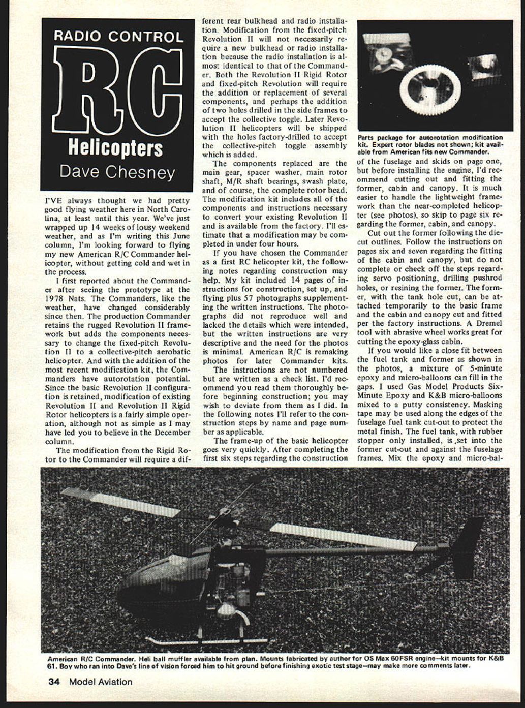
I've always thought we had pretty good flying weather here in North Carolina, at least until this year. We've just wrapped up 14 weeks of lousy weekend weather, and as I'm writing this June column, I'm looking forward to flying my new American R/C Commander helicopter without getting cold and wet in the process.
I first reported on the Commander after seeing the prototype at the 1978 Nats. The Commanders, like the weather, have changed considerably since then. The production Commander retains the rugged Revolution II framework but adds the components necessary to change the fixed-pitch Revolution II to a collective-pitch aerobatic helicopter. With the addition of the most recent modification kit, the Commanders have autorotation potential.
Conversion overview
Because the basic Revolution II configuration is retained, modification of existing Revolution II and Revolution II Rigid Rotor helicopters is a fairly simple operation, although not as simple as I may have led you to believe in the December column.
- Converting from the Rigid Rotor to the Commander will require a different rear bulkhead and radio installation.
- Converting from the fixed-pitch Revolution II will not necessarily require a new bulkhead or radio installation because the radio installation is almost identical to that of the Commander.
- Both the Revolution II Rigid Rotor and fixed-pitch Revolution II will require the addition or replacement of several components, and perhaps the addition of two holes drilled in the side frames to accept the collective toggle. Later Revolution II helicopters will be shipped with the holes factory-drilled to accept the collective-pitch toggle assembly which is added.
The modification kit includes all components and instructions necessary to convert your existing Revolution II and is available from the factory. I estimate that a modification may be completed in under four hours.
Components replaced
The components replaced in the conversion include:
- Main gear
- Spacer washer
- Main rotor shaft
- M/R shaft bearings
- Swash plate
- Complete rotor head
If this is your first RC helicopter kit
If you have chosen the Commander as a first RC helicopter kit, the following construction notes may help. My kit included 14 pages of instructions for construction, setup, and flying, plus 57 photographs supplementing the written instructions. The photographs did not reproduce well and lacked the details which were intended, but the written instructions are very descriptive and the need for the photos is minimal. American R/C is remaking photos for later Commander kits.
The instructions are not numbered but are written as a checklist. I recommend you read them thoroughly before beginning construction; you may wish to deviate from them as I did. In the notes below I'll refer to the construction steps by name and page number as applicable.
Frame-up and early construction
The frame-up of the basic helicopter goes very quickly. After completing the first six steps regarding the construction of the fuselage and skids on page one, but before installing the engine, I recommend cutting out and fitting the former, cabin, and canopy. It is much easier to handle the lightweight framework than the near-completed helicopter, so skip to page six regarding the former, cabin, and canopy.
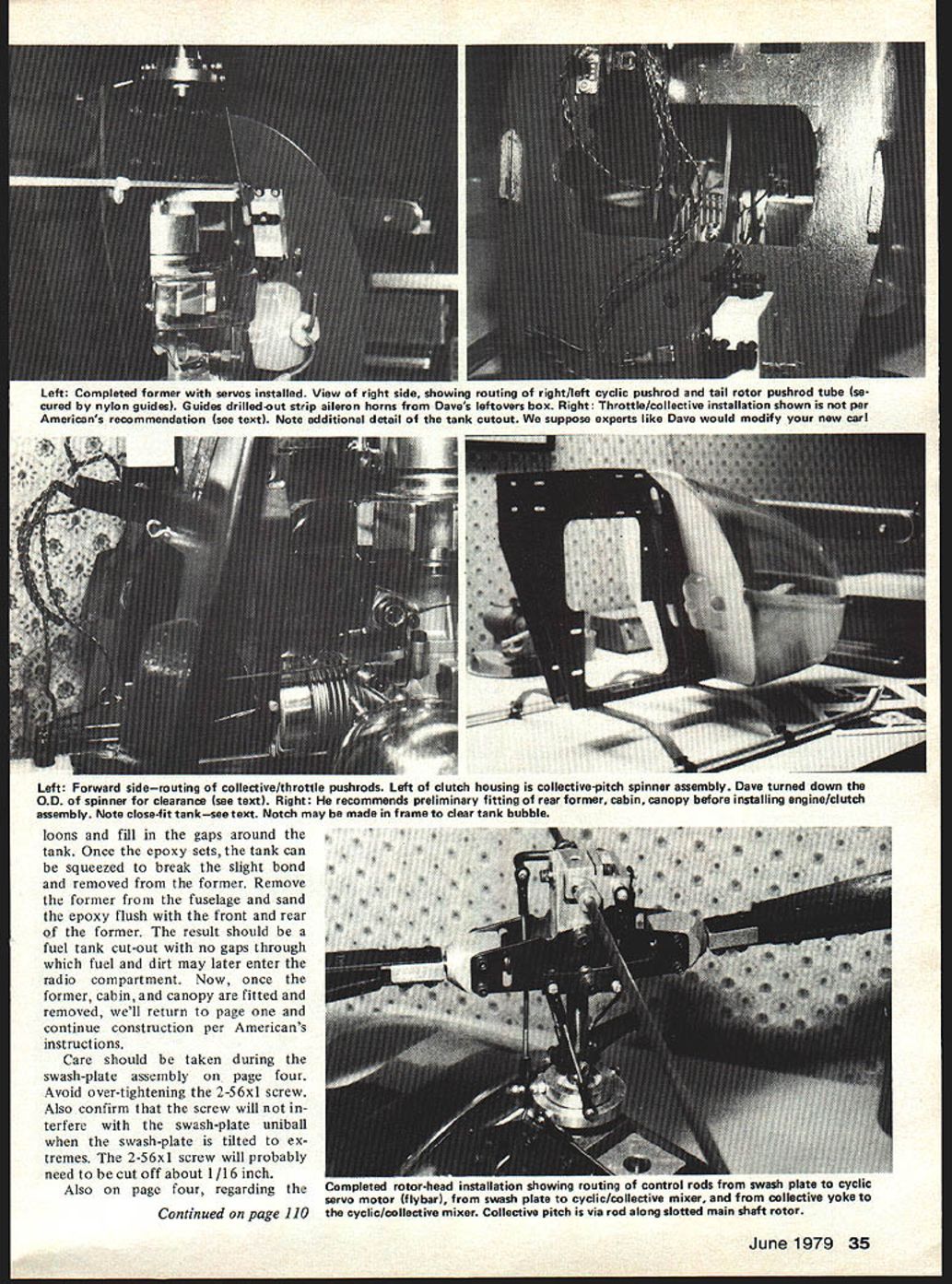
Cut out the former following the die-cut outlines. Follow the instructions on pages six and seven regarding the fitting of the cabin and canopy, but do not complete or check off the steps regarding servo positioning, drilling pushrod holes, or resining the former. The former, with the tank hole cut, can be attached temporarily to the basic frame and the cabin and canopy cut and fitted per the factory instructions. A Dremel tool with an abrasive wheel works great for cutting the epoxy-glass cabin.
Fuel tank and former fit
If you would like a close fit between the fuel tank and former as shown in the photos, a mixture of 5-minute epoxy and micro-balloons can fill in the gaps. I used Gas Model Products Six-Minute Epoxy and K&B micro-balloons mixed to a putty consistency. Masking tape may be used along the edges of the fuselage fuel tank cut-out to protect the metal finish.
The fuel tank, with rubber stopper only installed, is set into the former cut-out and against the fuselage frames. Mix the epoxy and micro-balloons to fill gaps around the tank. Once the epoxy sets, the tank can be squeezed to break the slight bond and the former removed. Remove the former and sand the epoxy flush front and rear; the result should be a fuel tank cut-out with no gaps through which dirt may later enter the radio compartment.
Once the former, cabin, and canopy are fitted, remove them and return to page one and continue construction per American's instructions. Care should be taken.
Swash-plate assembly
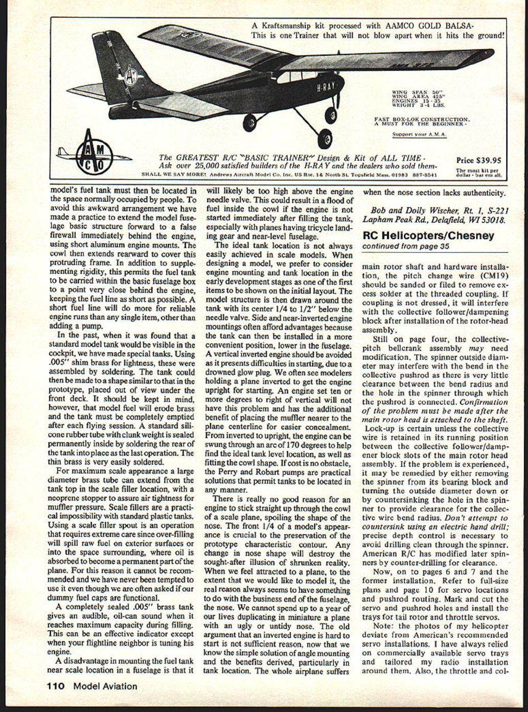
During the swash-plate assembly on page four, avoid over-tightening the 2-56 x 1 screw. Also confirm that the screw will not interfere with the swash-plate uniball when the swash-plate is tilted to extremes. The 2-56 x 1 screw will probably need to be cut off about 1/16 inch.
For the main rotor shaft and hardware installation, the pitch change wire (CM19) should be sanded or filed to remove excess solder at the threaded coupling. If the coupling is not dressed, it will interfere with the collective follower/damping block after installation of the rotor-head assembly.
Collective-pitch bellcrank and spinner clearance
Still on page four, the collective-pitch bellcrank assembly may need modification. The spinner outside diameter may interfere with the bend in the collective pushrod, as there is very little clearance between the bend radius and the hole in the spinner through which the pushrod is connected. Confirmation of the problem must be made after the main rotor head is attached to the shaft. Lock-up is certain unless the collective wire is retained in its running position between the collective follower/damper block slots of the main rotor head assembly.
If the problem is experienced, it may be remedied by either:
- Removing the spinner from its bearing block and turning the outside diameter down, or
- Countersinking the hole in the spinner to provide clearance for the collective wire bend radius.
Don't attempt to countersink using an electric hand drill; precise depth control is necessary to avoid drilling clean through the spinner. American R/C has modified later spinners by counter-drilling for clearance.
Servo locations and pushrod routing
Now, on to pages six and seven and the former installation. Refer to full-size plans and page 10 for servo locations and pushrod routing. Mark and cut the servo and pushrod holes and install the trays for tail rotor and throttle servos.
Note: the photos of my helicopter deviate from American's recommended servo installations. I have always relied on commercially available servo trays and tailored my radio installation around them. Also, the throttle and collective servo installations are described on the full-size plans.
Transcribed from original scans by AI. Minor OCR errors may remain.

