
Radio Control: Helicopters
Dave Chesney
Heliboy rotor head modification
The November column by Tim Peters included Nats coverage and a photo of a Heliboy rotor head modification. Tim described a modification, based on an idea by Bo Hinch and developed by Peyton Enloe, to eliminate problems with collective pitch arms that occasionally work loose from the blade axles after crashes. Because the arms are peened to the blade axles, they will change adjustment if abused, and eventually the standard pitch arm/blade axle assemblies must be replaced.
As far as I know, the Enloe modification is available from Peyton Enloe (326 E. March Drive, Lafayette, LA 70501) for about $30.00. For those who prefer to make their own, a similar modification is presented here by Glenn Scillian, Silver Spring, MD. Glenn, having experienced the problems described in Tim Peters' column, was impressed by the Enloe mod and developed his own version.
Materials and construction
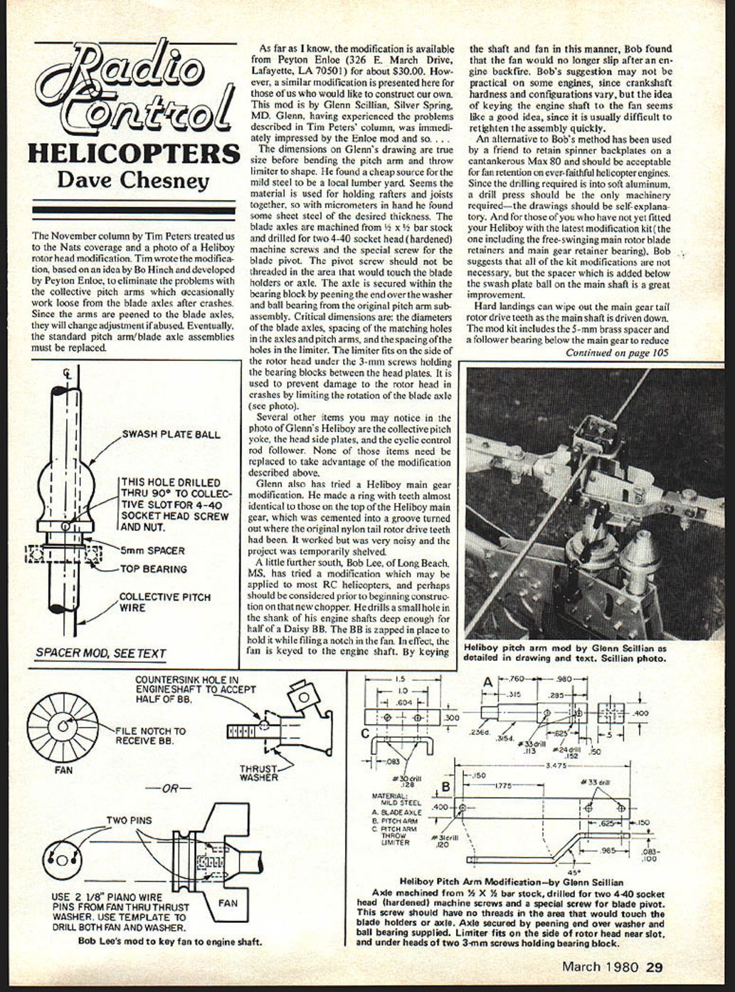
The dimensions on Glenn's drawing are true size before bending the pitch arm and throw limiter to shape. He found a cheap source for the mild steel at a local lumber yard; the material is used for holding rafters and joists together. Using micrometers, he located sheet steel of the desired thickness.
The blade axles are machined from 5/32 x 1/2 bar stock and drilled for two 4-40 socket head (hardened) machine screws and the special screw for the blade pivot. The pivot screw should not be threaded in the area that would touch the blade holders or axle. The axle is secured within the bearing block by peening the end over the washer and ball bearing from the original pitch arm subassembly.
Critical dimensions include:
- The diameters of the blade axles.
- The spacing of the matching holes in the axles and pitch arms.
- The spacing of the holes in the limiter.
The limiter fits on the side of the rotor head under the 3-mm screws holding the bearing blocks between the head plates. It prevents damage to the rotor head in crashes by limiting the rotation of the blade axle.
Other Heliboy items
In Glenn's Heliboy photo you may notice the collective pitch yoke, the head side plates, and the cyclic control rod follower. None of those items need be replaced to take advantage of the modification described above.
Glenn also tried a Heliboy main gear modification. He made a ring with teeth almost identical to those on the top of the Heliboy main gear and cemented it into a groove turned where the original nylon tail rotor drive teeth had been. It worked but was very noisy, so the project was temporarily shelved.
Engine shaft keying (Bob Lee)
Bob Lee of Long Beach, MS, has tried a modification that may be applied to most RC helicopters and might be considered before building a new chopper. He drills a small hole in the shank of his engine shafts deep enough for half of a Daisy BB. He zaps the BB in place to hold it while filing a notch in the fan. In effect, the fan is keyed to the engine shaft. By keying the shaft and fan this way, Bob found the fan would no longer slip after an engine backfire.
This method may not be practical on some engines, since crankshaft hardness and configurations vary, but the idea of keying the engine shaft to the fan is useful because it is usually difficult to retighten the assembly quickly after slippage.
An alternative to Bob's method has been used by a friend to retain spinner backplates on a cantankerous Max 80 and should be acceptable for fan retention on reliable helicopter engines. Since the drilling required is into soft aluminum, a drill press should be the only machinery required; the drawings should be self-explanatory.
Swash plate spacer and main gear protection
For those who have not yet fitted their Heliboy with the latest modification kit (the one including the free-swinging main rotor blade retainers and main gear retainer bearing), Bob suggests that not all kit modifications are necessary, but the spacer added below the swash plate ball on the main shaft is a great improvement.
Hard landings can wipe out the main gear tail rotor drive teeth as the main shaft is driven down. The mod kit includes a 5-mm brass spacer and a follower bearing below the main gear to reduce that probability, but Bob feels the spacer is sufficient to fix the problem in all but the hardest landings. The spacer, inserted below the swash plate ball and resting on the top main shaft bearing, raises the ball so that additional torque may be applied to the ball set screw. A socket head screw and nut through the ball and shaft may be used to replace the set screw for additional security. Drill the hole through the shaft at 90° to the pitch change slot.
The spacer can be made by cutting 5 mm from the landing gear tubing. Cut the tubing squarely and carefully to avoid getting the spacer out of round (see the drawing for detail). This modification locks the main shaft between the bearing blocks and raises the ball to a more appropriate position within the swash plate.
Set-up tape (Walt Schoonard)
Walt Schoonard sent a copy of the set-up tape mentioned last month. Beginners, particularly those with less sophisticated radios, will benefit from it. The tape is a very complete tutorial of initial set-up procedures. If you would like a copy, write to Walt at 3410 Meadowbrook Dr., Lyndhurst, OH 44124 and include a stamped, self-addressed envelope. The tape is aimed at Heliboy helicopter pilots, so if you're interested drop Walt a line.
Closing
Hope to present some modifications for the Kavan Jet Ranger by Ray Hostetler next month. See you then.
Dave Chesney Rt. 9, Box 621 A Greensboro, NC 27409
Transcribed from original scans by AI. Minor OCR errors may remain.

