
Radio Control: Helicopters
Dave Chesney
LAST month we began with a review of the similarities of RC helicopters and RC airplanes. Briefly, the airplane and helicopter, while in forward flight, respond to control inputs to their three basic flight controls in much the same way. Once you've mastered hovering your helicopter and progress to forward flight, things get a little easier—but for now, all helicopter flights should begin and end with a transition through hovering flight.
So now we leave the airplane in a cloud of dust as it quickly moves down the runway and lifts off in relentless pursuit of forward flight. We, on the other hand, will struggle to learn how to make the helicopter lift off and hover. Please don't hover in that dirty air long: the fine particles picked up by the rotor and mixed with the engine exhaust will cover the machine with an excellent abrasive compound. Choose the flying site carefully, use an engine air intake filter, and clean the helicopter after flying.
As you remember, last month we discussed briefly the collective and cyclic controls of the helicopter. For those beginning with "fixed pitch" helicopters, the proper term is "fixed collective pitch." Even helicopters described as fixed collective pitch main rotor systems have a variable collective pitch mechanism for the tail rotor. The tail rotor uses collective pitch to vary thrust and provide yaw control. The tail rotor collective is comparatively simple: both blades are moved collectively from negative pitch to positive pitch while they spin.
Usually the kit instructions will note the approximate neutral pitch setting of the tail rotor collective so that, in a hover, the thrust provided is just enough to overcome torque. Differences in main rotor pitch and engine speed combinations, plus other factors, mean the neutral setting will probably never perfectly balance the tendency of the fuselage to rotate opposite to the main rotor—and that is why the tail demands much attention during the hover. Collective pitch control of the tail rotor is necessary (although the same result could be achieved by fixing the tail rotor collective and varying tail rotor speed; see last month), and although mechanisms vary slightly, the function of variable pitch is the same (see tail rotor sketch).
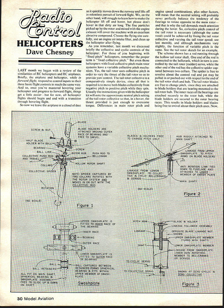
Tail rotor mechanism (example)
- A rod runs through the hollow tail rotor shaft.
- One end of the rod connects to a bellcrank controlled by the tail rotor (rudder) servo.
- The other end of the rod has the collective spider captured between two collars. The spider can revolve about the control rod and be pulled in or pushed out relative to the tail rotor shaft hub.
- Tail rotor blades attach to blade holders that are bearing-mounted to the tail rotor hub. The inner bearing races attach to the hub; the blade holders attach to the outer races. This lets the blade holders and blades swivel about their pitch axes.
- Linkage from the collective spider connects to the tail rotor blade holders. Movement of the spider causes the blades to swivel and change pitch collectively.
The tail rotor system is a good example of a rigid rotor system.
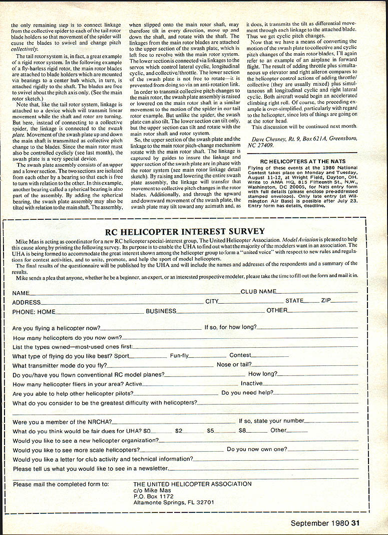
Flybarless rigid main rotor and the swash plate
A flybarless rigid rotor follows the same basic idea: the main rotor blades are attached to blade holders mounted via bearings on a center hub which is attached rigidly to the main shaft. The blades are free to swivel about the pitch axis only. Like the tail rotor, linkage attached to a device transmits linear movement along the shaft while the shaft and rotor are turning. Instead of connecting to a collective spider, the linkage is connected to the swash plate. Movement of the swash plate up and down the main shaft is transmitted as collective pitch change to the blades.
Since the main rotor must also be controlled cyclically, the swash plate is a very special device. The swash plate assembly consists of upper and lower sections isolated from each other by a bearing so that the upper section can revolve with the main rotor while the lower section is attached to the control linkages and servos. A spherical bearing is also part of the assembly; it allows the swash plate to tilt relative to the main shaft. Slipped onto the main rotor shaft, the assembly may tilt in any direction, move up and down the shaft, and rotate.
Linkages from the main rotor blades attach to the upper section of the swash plate, which revolves with the rotor. The lower section is connected via linkages to the servos that control:
- lateral cyclic
- longitudinal cyclic
- collective (often mixed with throttle)
The lower section of the swash plate is prevented from rotating by an anti-rotation link tied to the fuselage.
In order to transmit collective pitch changes to the main rotor, the swash plate assembly is raised or lowered on the main rotor shaft in a similar motion to the spider in the tail rotor example. Unlike the spider, however, the swash plate can also tilt. When the swash plate tilts toward any azimuth, that tilt is transmitted as differential movement through each linkage to the attached blades, producing cyclic pitch changes.
So:
- Raising and lowering the swash plate produces collective pitch changes in the blades.
- Tilting the swash plate produces cyclic pitch changes that tilt the rotor disk and control attitude.
The linkage between the upper swash plate and the main rotor pitch mechanism is captured by guides to ensure the swash plate and rotor system remain in phase (see main rotor linkage detail sketch).
Control analogy and transition to forward flight
Now that we have a means of converting swash plate motion into collective and cyclic pitch changes of the main rotor blades, an airplane analogy can help. Adding throttle plus up elevator and right aileron in an airplane roughly compares to adding throttle/collective (usually mixed) plus simultaneous rearward longitudinal cyclic and right lateral cyclic on a helicopter. Both aircraft would begin an accelerated climbing right roll. Of course, this is an oversimplification—especially for the helicopter, since many forces interact when the rotor tilts and the machine responds.
This discussion will be continued next month.
Dave Chesney Rt. 9, Box 621A Greensboro, NC 27409
Transcribed from original scans by AI. Minor OCR errors may remain.

