
Radio Control: Helicopters
Dave Chesney
In the last column we looked at the collective pitch mechanism for changing the pitch of the tail rotor and introduced some similarities between tail rotor collective and the main rotor collective of two-blade "rigid" rotor systems. The flybarless two-blade "rigid" rotor system has been chosen because it is generally less mechanically complicated than rotor systems using a flybar. In a flybarless system control input is introduced directly to the rotor blades rather than through the flybar (sometimes called a servo rotor). The flybarless system is also most like the tail rotor, since the blades are free to pivot about the feathering axis but are otherwise rigidly attached to the rotor hub.
However, "rigid" rotors are not truly rigid, as you will see when we introduce cyclic pitch changes to the rotor for control purposes.
Collective Pitch and the Swash Plate
Last month we described how main rotor collective pitch changes are transmitted by the servo through the sliding swash plate to the pitch arms of the rotor blades. Since the linkages from the swash plate to the blades move equally, both blades change pitch equally as the swash plate moves up and down the main rotor shaft (similar to the action of the collective spider in the tail rotor example).
The sliding swash plate method for collective changes is not the only way to accomplish this, but it is fairly simple. In the flybarless rotor example, mixing is accomplished with bellcranks within the fuselage and below the non-revolving part of the swash plate.
Cyclic Control and a Correction to a Previous Sketch
I made a mistake in a sketch in the July column regarding cyclic control — specifically the position of the rotor blades at maximum and minimum pitch for right roll. The following clarifies that error.
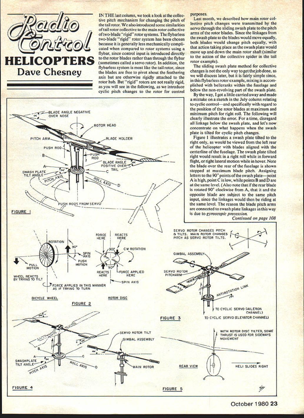
For a moment, disregard all linkage below the swash plate and concentrate on what happens when the swash plate is tilted for cyclic pitch changes. Figure 1 illustrates a swash plate tilted to the right only, as viewed from the left rear of the helicopter with the blades aligned with the fuselage centerline. The swash plate tilted right would result in a right roll while in forward flight, or right lateral motion while in hover.
Assign letters to the 90° points of the swash plate: point A is high, point C is low, while points B and D are at the same level. Note that if the rear blade is rotated 90° clockwise from A, that blade and the opposite blade are subject to the same pitch input, since the linkages would then be riding at the same level. The reason the blade pitch arms are connected to swash plate linkages in this way is due to gyroscopic precession.
Gyroscopic Precession and Rigidity in Space
The spinning rotor acts as a gyroscope, which is a plus for stability because a gyroscope resists forces that would change its axis of rotation. The faster the rotor spins, the more resistance to change — one reason there has been a trend to higher rotor speeds in recent years and a strong argument for variable collective pitch rather than fixed collective pitch. With variable collective pitch, rotor speed is approximately constant; fixed collective pitch rotors must speed up and slow down to change lift.
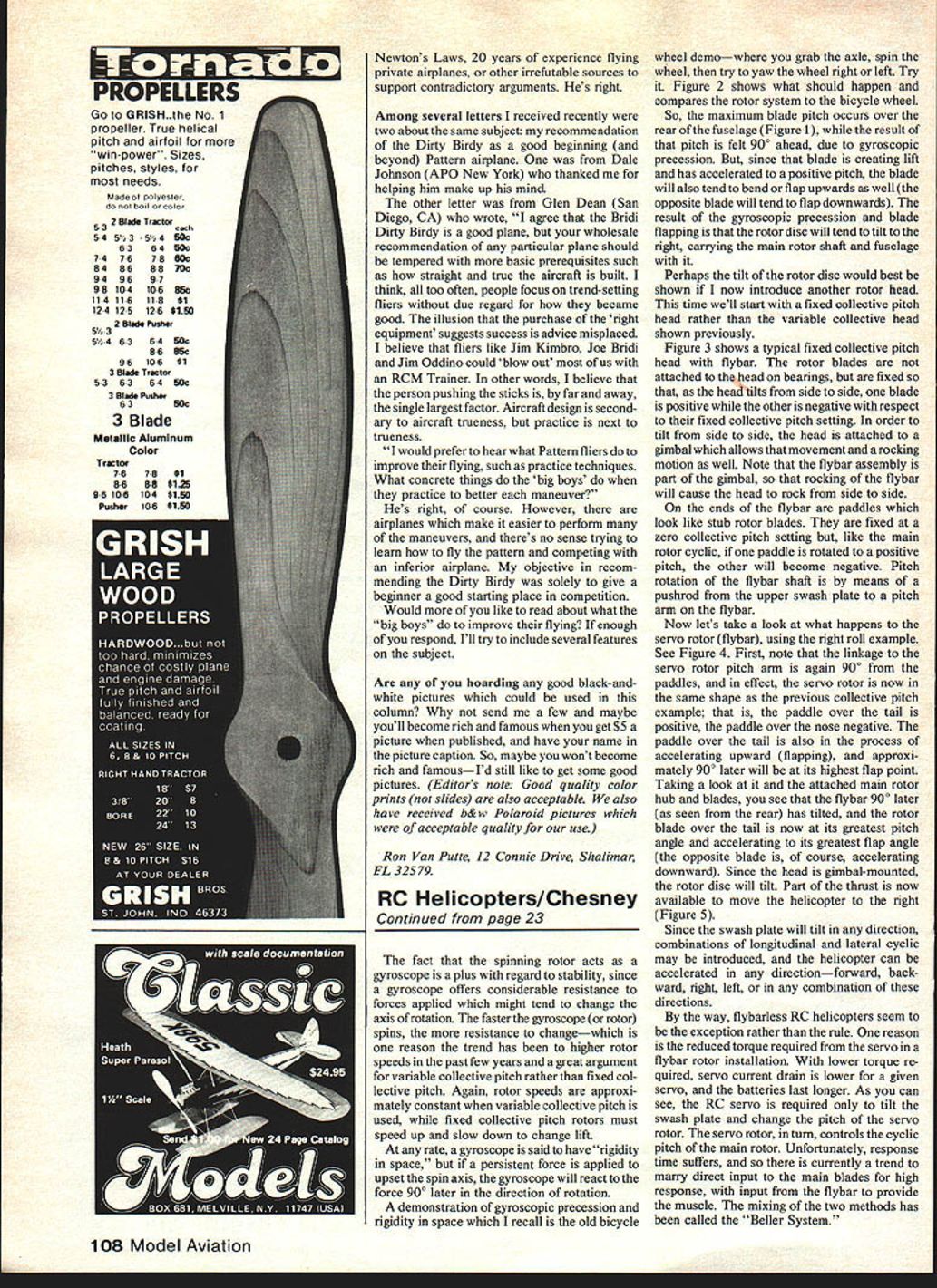
A gyroscope is said to have "rigidity in space," but if a persistent force is applied to upset the spin axis, the gyroscope will react to that force 90° later in the direction of rotation. A familiar demonstration is the bicycle wheel demo: grab the axle, spin the wheel, then try to yaw the wheel right or left. The effect shows gyroscopic precession. Figure 2 compares that demonstration to the rotor system.
In the swash-plate example (Figure 1), the maximum blade pitch occurs over the rear of the fuselage, but the result of that pitch is felt 90° ahead due to gyroscopic precession. Because the blade at positive pitch is creating lift, it will tend to bend or flap upward (the opposite blade will tend to flap downward). The combined effect of gyroscopic precession and blade flapping causes the rotor disc to tilt to the right, carrying the main rotor shaft and fuselage with it.
Fixed Collective Pitch Head and the Flybar
Consider a different rotor head: a typical fixed collective pitch head with a flybar (Figure 3). In this design the rotor blades are fixed to the head rather than attached on bearings, so as the head tilts one blade becomes positive and the other negative relative to their fixed collective pitch setting. To allow tilt and rocking motion the head is attached to a gimbal. The flybar assembly is part of that gimbal, so rocking of the flybar will cause the head to rock from side to side.
On the ends of the flybar are paddles that resemble small rotor blades. They are fixed at zero collective pitch but, like the main rotor cyclic, if one paddle is rotated to a positive pitch the other becomes negative. Pitch rotation of the flybar shaft is effected by a pushrod from the upper swash plate to a pitch arm on the flybar.
How the Flybar Produces Cyclic
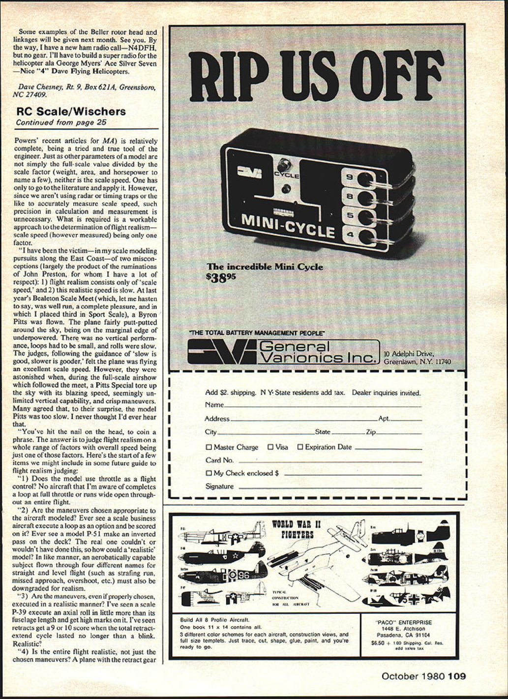
Using the right-roll example (Figure 4), note that the linkage to the servo rotor (flybar) pitch arm is again 90° from the link to the paddles. In effect, the servo rotor is in the same shape as the previous collective pitch example: the paddle over the tail is positive while the paddle over the nose is negative. The paddle over the tail is also flapping upward and, approximately 90° later, will be at its highest flap point.
Looking at the flybar and the attached main rotor hub and blades, you see that the flybar, 90° later (as seen from the rear), has tilted so that the rotor blade over the tail is at its greatest pitch angle and accelerating to its greatest flap angle (the opposite blade is accelerating downward). Because the head is gimbal-mounted, the rotor disc tilts and part of the thrust is directed to move the helicopter to the right (Figure 5).
Since the swash plate can tilt in any direction, combinations of longitudinal and lateral cyclic may be introduced, and the helicopter can be accelerated in any direction — forward, backward, right, left, or any combination.
Flybar vs Flybarless and the Beller System
Flybarless RC helicopters are still the exception rather than the rule. One reason is the reduced torque required from the servo in a flybar rotor installation. With lower torque required, servo current drain is lower for a given servo and batteries last longer. In a flybar system the RC servo is required only to tilt the swash plate and change the pitch of the servo rotor; the servo rotor, in turn, controls the cyclic pitch of the main rotor. The trade-off is response time: flybar systems tend to be slower to respond.
There is a current trend to marry direct input to the main blades for high response with input from the flybar to provide mixing. This hybrid approach has been called the "Beller System." Examples of the Beller rotor head and linkages will be given next month.
Closing and Contact
See you next month.
By the way, I have a new ham radio call — N4DFH, but no gear yet. I'll have to build a super radio for the helicopter à la George Myers' Ace Silver Seven.
Dave Chesney Rt. 9, Box 621A Greensboro, NC 27409
Key Points
- Flybarless systems are mechanically simpler and provide direct blade control, but require more servo torque and can reduce battery life.
- Flybar systems reduce servo torque and battery drain but can be slower to respond.
- Gyroscopic precession causes control inputs to be felt 90° later in the direction of rotation, and blade flapping couples with precession to tilt the rotor disc.
Transcribed from original scans by AI. Minor OCR errors may remain.

