

Radio Control: Helicopters
Dave Chesney
System 80 concept
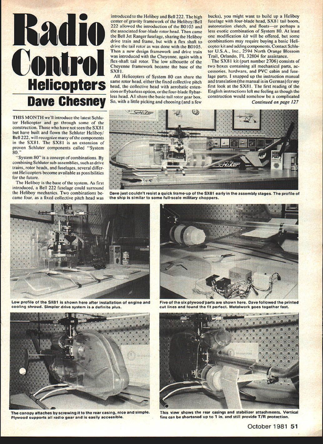
THIS MONTH we'll introduce the latest Schluter Helicopter and go through some of the construction. Those who have not seen the SX81 but have built and flown the Schluter Heliboy/Bell 222 will recognize many of the components in the SX81. The SX81 is an extension of proven Schluter components called "System 80."
"System 80" is a concept of combinations. By combining Schluter sub-assemblies, such as drive trains, rotor heads, and fuselages, several different helicopters become available as possibilities for the future.
The Heliboy is the base of the system. As first introduced, a Bell 222 fuselage could surround the Heliboy mechanics. Two combinations became four, as a fixed collective pitch head was introduced to the Heliboy and Bell 222. The high center-of-gravity framework of the Heliboy/Bell 222 allowed the introduction of the BO105 and the associated four-blade rotor head. Then came the Bell Jet Ranger fuselage, sharing the Heliboy drive train and frame, but with a flex shaft to drive the tail rotor as was done with the BO105.
Then a new design framework and drive train was introduced with the Cheyenne, again with a flex-shaft tail rotor. The low silhouette of the Cheyenne framework became the base of the SX81.
All helicopters of System 80 can share the same rotor head: either the fixed collective-pitch head, the collective head with aerobatic extension or flybarless option, or the four-blade flybarless head. All share the basic tail-rotor gearbox. So, with a little picking and choosing (and a few bucks), you might build up a Heliboy fuselage with a four-blade head, SX81 tail boom, autorotation clutch, and floats—or perhaps a less exotic combination of System 80.
At least one modification kit will be offered, but some combinations may require buying a basic helicopter kit and adding components. Contact Schluter U.S.A., Inc., 2594 North Orange Blossom Trail, Orlando, FL 32804 for assistance.
The SX81 kit
The SX81 kit (part number 2706) consists of two boxes containing all mechanical parts, accessories, hardware, and PVC cabin and fuselage parts. I snapped up the instruction manual and translation (the manual is in German) for my first look at the SX81. The first reading of the English instructions left me feeling as though the construction would somehow be complicated due to the wording and liberal reference to various screw sizes and part numbers. However, things started to fall in place as each package of parts was opened for the stage referenced in the booklet.
Tools and initial notes
For the initial framework construction I used, in addition to the tools supplied with the kit:
- a screwdriver
- needle-nose pliers
- a small X-Acto file set
- a plastic grease gun filled with the special grease supplied with the kit
The little grease gun was previously sent by Miniature Aircraft Supply (available for $1.50) and was extremely useful for putting grease where I wanted it. As with the Heliboy article a few years back, I'll limit comments to those stages where I experienced difficulty or found something noteworthy.
The framework of the SX81 is the basis of the low-profile PVC fuselage, which will later surround the mechanics. The engine position is shaft down, versus shaft up as with the Heliboy. This engine position yields not only the low profile but also, with the associated drive system, a simpler drive system to set up. The drive system is virtually self-aligning.
Construction notes by stage
#### Stage 3 Step 3 gave me some difficulty, beginning with the use of washers to provide clearance of gear (170) to the lower side frames—this after determining clearance of the clutch housing and nylon gear (170). Once both were installed on the clutch and shaft assembly (169), I found clearances required:
- one washer between the clutch and clutch bell (instructions call for one or two washers)
- two washers between clutch bell and upper bearing block (per instruction)
- three washers between the lower bearing block and nylon gear (instructions do not specify)
This arrangement provided running clearance between the special nuts in the nylon gear and the lower side frames of the fuselage. Once the nylon gear is attached to the clutch/shaft assembly using special nuts and M4x15 screws, assembly sequence from the long end of the shaft is: one or two washers, then check clutch housing to nylon gear clearance; two washers, then bearing block 131 (Brg. down); then from bottom three washers and bearing block 131 (Brg. up). The balance of assembly through Stage 4 was no problem.
#### Stage 5 Stage 5 toggle lever installation called for an M3x35 screw to retain the lever (476) and support bearing block to the fuselage side frames. The photo instruction showed an M3 self-lock nut screwed to the M3x35; however, I found the exposed threads of the M3x35 insufficient to engage the self-lock and chose to use a standard M3 nut and Blue Loctite instead.
The photo of Stage 5 also showed the compensating lever (358) attached to toggle (476). The written instructions did not indicate that attachment. Although Bag 5 contained the screws and washers to install the arm—no arm. Check Bag 5; if the arm is missing, contact Schluter U.S.A. for a prompt replacement.
#### Stage 6 Again I found self-lock nuts would not engage fully, so I chose to use only one washer on each M3x30 screw retaining the PVC bearing block between the side frames.
#### Stage 7 If you have built a Heliboy you'll appreciate Stage 7. The lineup of the drive gear is certainly easier than the proper lineup of the Heliboy starting shaft. The only comment here is that the design of the drive unit requires a .61 engine with a 1/4-in. crankshaft. If you have a favorite engine type as I do, the metal gear (173) may require some machining (don't just drill—please use a lathe and dial indicator) to fit the crankshaft. I had to machine a counterbore in the gear for my old standard .4 Max 60FSR engine which had a 1/4-in. stub shaft in its crankshaft. Watch engine selections; that's a 1/4-in. shaft right down to the thrust washer, or some machining time to make the favorite engine fit. Schluter U.S.A. will bore gears to special fit if requested when a new kit or spare gear is ordered.
#### Stage 9 For gosh sakes, pay attention to the gear arrangement and instructions. The tail-rotor (T/R) drive is reduction gearing! All Schluter helicopters—Heliboy, SX81, Cheyenne and Miniboy—use reduction gearing. Putting gears in backwards is dangerous, since the speed could throw T/R blades.
#### Stage 10 For Stage 10, see the August MA column for the latest Schluter T/R modification, if necessary. Although parts are supplied for the latest mod, the instructions were for the earlier version prior to the black plastic blade holders and associated retainers. Watch out to make sure the Loctite is applied to the hub and not to the screw; otherwise, the Loctite may wick into the bearing.
#### Stages 11–13 Stages 11, 12 and 13 gave no problem, but I'll again mention the head lock device (see September) which I find makes a dandy assembly aid. The head lock keeps the flybar from pivoting while installing other head components. As usual, I installed Option 13 to the standard head. The leftover pieces are for the flybarless modification which requires special weighted rotor blades. How about that: three rotor heads in one kit. I might add that some subtle changes to the head have been made since the Heliboy, but since the assembly sequences and functions remain the same, I will not detail those improvements.
#### Stage 14 Go ahead and reinforce the blade root with fiberglass cloth and resin or fiberglass cloth and Hot Stuff.
#### Stage 15 The tank clamps should be band-bent so they hold the tank snugly. If the clamps are just formed around the tank, the fit will be loose and the tank will not be secured properly.
#### Stage 16 At this point, I jumped the gun and started cutting out the servo mounts, plastic casings and such, just to see how everything would fit. The plywood parts were cut to outline and drilled for mounting to the frame only. The photo shows that result—everything fits great. And, so, back to the construction sequence.
I really liked the arrangement for mounting the radio equipment. As you can see, there is enough room to mount a fair amount of gear on and in the plywood plates. The final radio installation will be shown in another column when we'll try out the SX81 with the Watson sensor installed. This note on building (or re-covering) also applies—plan the installation carefully. In this case, I stuck with the locations recommended by Schluter for four servos, battery, receiver and switch. There is room to install a fifth servo if desired and, of course, an accessory device such as the Watson sensor.
#### Stage 17 The fuselage casings are molded PVC. I chose to join the halves per the instructions using PVC glue (Elmer's Plastic Mender) although I understand many builders prefer Hot Stuff. I must admit Hot Stuff (or equivalent) makes more sense, since the casings can be aligned prior to the application of the glue, which is wicked in. Clothespins and straight pins may be used as an alignment and clamping method regardless of the glue type chosen.
Once the casings are cut out, joined, and trimmed, the finishing touches are applied. I chose to try Pactra Formula U aviation yellow spray—and blew it. Formula U is a great product when applied properly, but on my first try I went a little thick on the first coat. Wow, will it run! Then I read the instructions. Several thin coats give a better finish. The rear fuselage looked much better on the first try by spraying one light coat, then a following coat slightly heavier after waiting about 15 minutes.
Preparation of the plastic surface is important. For best results, roughen the plastic to be painted using Scotch-Brite pads, which are available at body shops and auto supply stores. Acceptable finishes may be applied using epoxy paints or automotive acrylic; but the surface coat must be primer. A tinted canopy look can be had by applying Testors transparent colors from inside the canopy.
Schluter's stick-on decals are not fuel-proof, so they must be wiped off after each flight or protected with a clear fuel-proof coating.
#### Stage 18 Pushrod installation is straightforward. Here, again, more detail will be in a later column.
Final notes and events
Well, that's about it. As soon as I repaint the front end of this bird, I'm going flying. Maybe the SX81 and I will get good enough to fly in the Schluter Cup Eastern Helicopter Contest in Statesville, NC on October 3 and 4. If you'd like to join us, contact:
- Juette Forehand, CD, (704) 872-2249
- Billy Harris, (704) 527-2843
- Walt Schoonard, (305) 422-1531
- Dave Chesney, (919) 668-0107
All helicopter fliers are welcome no matter what machines are flown or the proficiency level of the pilot.
Dave Chesney Rt. 9 Box 621A Greensboro, NC 27409
Transcribed from original scans by AI. Minor OCR errors may remain.

