
Radio Control: Helicopters
Dave Chesney
Introduction — Vibration and the beginning flier
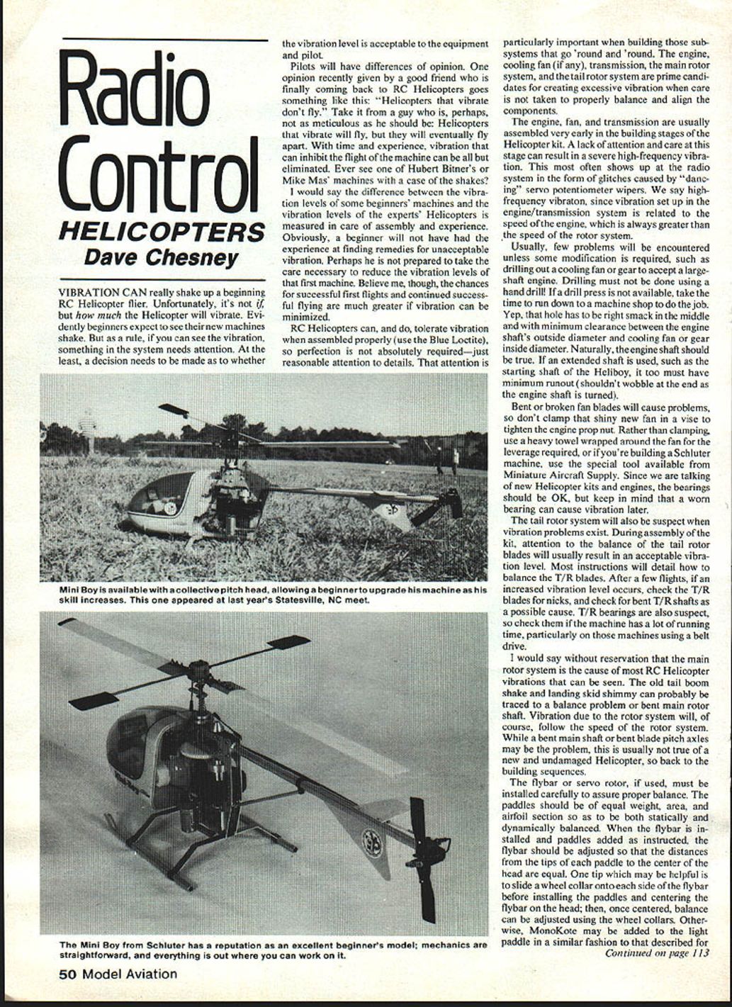
Vibration can really shake up a beginning RC helicopter flier. Unfortunately, it's not a matter of if your helicopter will vibrate, but how much. Beginners often expect their new machines to shake, but as a rule, if you can see the vibration, something in the system needs attention. At the least, decide whether the vibration level is acceptable for both the equipment and the pilot.
Pilots will have differing opinions about acceptable vibration. One friend summed it up: "Helicopters that vibrate don't fly." In reality, helicopters that vibrate will fly, but they will eventually wear themselves apart. With time and careful assembly, vibration that inhibits flight can be largely eliminated.
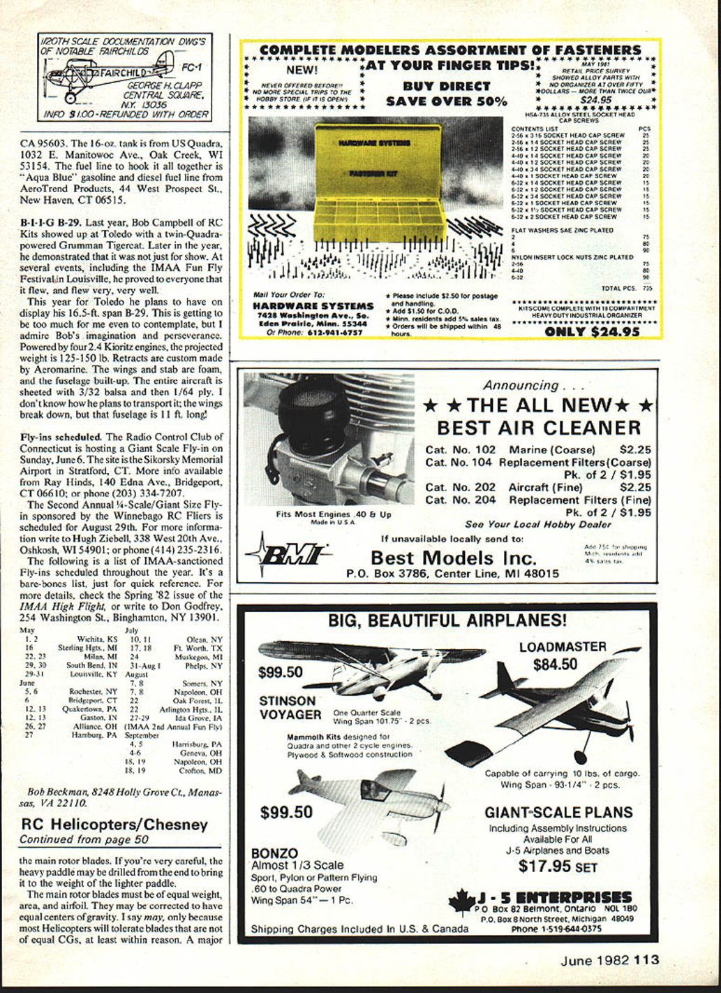
RC helicopters can tolerate some vibration when assembled properly (use Blue Loctite where recommended), so perfection isn't required — but reasonable attention to detail is. Pay particular attention to subsystems that rotate: the engine and cooling fan, the transmission, the main rotor system, and the tail rotor system. These are prime candidates for creating excessive vibration if components aren't properly balanced and aligned.
Primary sources of vibration
- Engine, cooling fan, and transmission
- These are usually assembled early in the build. Lack of care here can produce high-frequency vibration that often shows up as radio glitches (dancing servo potentiometer wipers).
- High-frequency vibration relates to engine/transmission speed, which is always higher than rotor speed.
- Modifications (for example, enlarging a fan or gear bore for a large-shaft engine) must be done precisely. Drilling must NOT be done with a hand drill—use a drill press or have a machine shop do the job. The hole must be concentric with minimal clearance to the engine shaft.
- The engine shaft should be true. Extended shafts (e.g., Heliboy starting shafts) must have minimal runout.
- Bent or broken fan blades cause vibration. Do not clamp a new fan in a vise to tighten the prop nut; protect the fan with a heavy towel or use a special tool (e.g., the Schluter tool from Miniature Aircraft Supply).
- Bearings in new kits are usually fine, but worn bearings will cause vibration later.
- Tail rotor system
- Balance the tail rotor blades during assembly; most kits include instructions.
- After several flights, check the T/R blades for nicks, bent T/R shafts, and worn T/R bearings—especially on machines with lots of running time or belt drives.
- Main rotor system
- The main rotor is the cause of most visible helicopter vibration (tail boom shake, skid shimmy).
- Vibration from the rotor system follows rotor speed. Causes include bent main shaft or bent blade pitch axles.
- In new, undamaged helicopters, rotor-system vibration usually traces back to assembly and balancing issues.
Flybar, servo-rotor, and flybar paddle balance
- Install the flybar (or servo rotor) carefully to ensure proper balance.
- Paddles should be equal in weight, area, and airfoil, and they should be statically and dynamically balanced.
- After installing the flybar and paddles as instructed, adjust so the distances from each paddle tip to the center of the head are equal.
- Helpful trick: slide a wheel collar onto each side of the flybar before installing paddles; center the flybar on the head, then fine-tune balance with the collars.
- Alternatively, use MonoKote to add weight to the lighter paddle, or carefully drill the heavier paddle from the end to reduce weight.
Main rotor blade balance and alignment
- Blades should be of equal weight, area, and airfoil. Correcting blade centers of gravity (CGs) produces the smoothest system—especially important on flybarless helicopters where blade CG is critical.
- For most beginner setups (non-flybarless), the easiest method is to wrap MonoKote or similar material around the light blade to balance the rotor system. This static balancing is fundamental and typically shown in the instructions — take your time to get it right.
Lead/lag, blade holders, and coning angle
- Lead/lag adjustment
- Improper lead/lag setup causes vibration, particularly when blades are rigidly fixed and unable to lead/lag freely.
- Blade holders (single-bolt or rigid types) should be mounted so the holders are parallel to the blade leading edge. Most manufacturers supply pre-drilled blades with only slight alignment needed.
- Coning angle
- The coning angle is analogous to dihedral on an airplane wing; it reduces bending caused by lift but should not be increased beyond the designer’s recommendation to gain perceived stability.
- The designer chooses coning based on blade centrifugal force and the helicopter's nominal weight. Increasing coning beyond specs can cause blades to twist and create apparent vibration, especially on variable-collective-pitch heads.
- Set the coning angle as recommended in the instructions.
- Teeter spring and head level
- If a teeter spring is used, adjust its bracket so the rotor head is level. A bent or loose teeter spring can rotate and make the head off-level by twice the original error.
Static versus aerodynamic balance — blade tracking
- Proper static balancing of rotating components during build typically leads to acceptable dynamic balance. Before aerodynamic forces take effect (i.e., when everything first spins up), the helicopter should be relatively smooth.
- Aerodynamic balance means getting the blades to track. If pitch angles are set per instructions, tracking usually requires only a slight adjustment of one blade’s incidence.
- Typically, the blade running high in the track is corrected by reducing its pitch angle.
- To identify which blade is high, use high-visibility markings on the tips:
- Dayglow MonoKote is useful for static balancing and makes blade tips easy to distinguish.
- Use contrasting colors on the tips (e.g., black on one blade, yellow on the other). Avoid low-contrast pairs like light blue and gold.
Assembly checklist (quick)
- Use Blue Loctite where recommended.
- Ensure engine shaft and any extended shafts have minimal runout.
- Have any required drilling done on a drill press or by a machine shop.
- Protect cooling fans when tightening nuts—don’t clamp them in a vise.
- Balance and inspect tail rotor blades and bearings.
- Statically balance flybar paddles and main blades; correct CGs if possible.
- Set lead/lag and coning angle per instructions.
- Track blades and make small pitch adjustments as needed.
- Recheck bearings and shafts after several flights.
Additional resources and closing
Gorham Model Products (GMP) offers a roughly 20-minute VHS tape that, while promotional, contains some excellent flying sequences. GMP supplies the tape for $30 (refundable upon return). It can make a good club program to stir local interest.
Smooth flying. See you next month.
Dave Chesney Rt. 9, Box 621A, Greensboro, NC 27409
Transcribed from original scans by AI. Minor OCR errors may remain.

