
Radio Control: Helicopters
Larry Jolly
Superior
SUPERIOR. When someone markets a product and gives it that kind of name, you know they must be pretty sure of themselves — and their product. Thinking about it, this really isn't too much of a boast from someone like Dieter Schluter, who first gave us Radio Control Helicopters and then went on to produce such classic machines as the Helibaby and the Heliboy.
The Superior is Dieter's latest design and may end up being his masterpiece. If you were to just scratch the surface, you would see that it is a highly refined, competition aerobatic radio-controlled helicopter. Mechanical features include:
- 1.4-meter rotor diameter
- 40 shielded ball races
- Bell-Hiller steering
- Double-sided main gear
- Full-envelope flight performance
- Heavy-duty ball links throughout
- Exceptional cooling system
- Anodized frame, skids, and boom pieces
- Autorotation as standard equipment
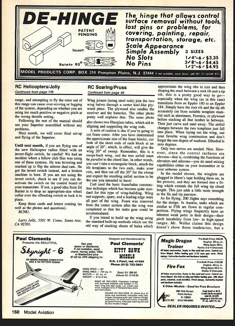
- Aesthetic, aerodynamic fuselage cabin
If you take all the above features, add countless hours of clever German engineering, a 10 cc motor and a modern five-servo helicopter radio, you have a Superior.
I've heard the claim that the Superior is nothing more than a beefed-up Heliboy. I don't agree. While these two machines share some common ideas, the Superior is a different machine. While the Heliboy was the machine for the Seventies, ushering in high-level helicopter aerobatics, the Superior is more the machine for the Eighties — a machine with more to offer than just loops and rolls.
The first thing that came to my mind as I built the Superior was that Schluter had designed a machine that was made to perform but not wear out too quickly. Literally every moving part is supported by ball bearings. This quality will give the machine the ability to last — of course, barring any accidental damage.
Because describing the necessary set-up required on the Superior takes quite a bit of space, I will use the remainder of this column talking about assembling the machine and will cover flying next month.
Building and initial impressions
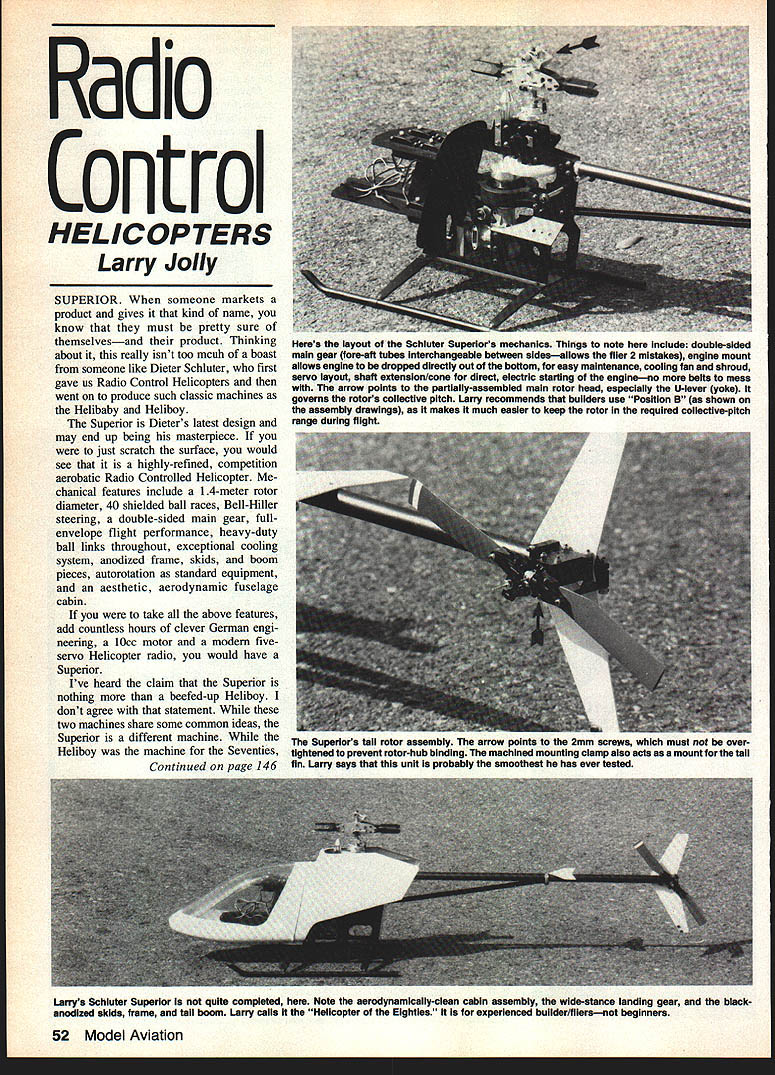
The Superior is carefully packaged in two boxes. One box contains the mechanics and the second contains the now-familiar Schluter plastic cabin. All parts arrived safely; the packaging is more than adequate. Dieter made a wise decision when he drew the plan sheet for the helicopter mechanics. The drawing is laid out as a two-sided, exploded isometric showing all parts and their locations. The drawing greatly aids assembly.
Building the Superior should not be tough for someone who has a few helicopters under his belt, especially if he has previously built a Schluter product. Not that the instruction booklet supplied is inadequate — it's just that the first-time builder may have some problems in the areas where the writer of the manual assumes the builder is familiar with the task at hand. A point that comes to mind is the main rotor blade balancing, for instance. The manual states, "We take it for granted that the basic technique of the balancing procedure is known." I feel that this is too vague, since balancing the rotors is extremely important for a properly flying machine.
The Superior is assembled in 14 primary steps. Below are the steps that might need more explanation or where the builder should be careful.
- Sequence one: securing the pitch and roll bellcranks to the side frames.
- Be careful that the bellcranks move freely but that there is no slop.
- Sequence two: applying the swash plate, pitch-change mechanism, and the follower to the main shaft.
- Be sure you follow the proper sequence and do not become confused, as some parts (for instance the swash plate) are preassembled at the factory, though the drawing may make it appear that they must be assembled by the builder.
- Step five: starting shaft run-out.
- This is extremely important for a smooth-running machine. Follow Schluter's instructions and make sure the starting shaft has the absolute minimum in run-out ("wobble"). If your completed machine has a high-frequency vibration, you can almost always trace the problem to a starting shaft and clutch assembly running out.
- Step six: clutch bell end-play.
- Make sure the clutch bell has 1 mm of end-play when completely assembled and mounted in place.
- Step seven: engine clearance and cooling.
- When trimming part 298, remove just enough material for clearance. The cooling air must be guided around the cylinder for proper cooling.
- Step eight: fuel tank fittings.
- Be careful not to drill oversize holes in the tank. The threaded plate is mounted so the bumps on the flat fit against the tank wall, and the threaded shank points toward the center of the tank. Use silicon seal on the tank connections: you want a leakproof tank, especially if you are running pressure.
- Step ten: rotor hub mounting and bearings.
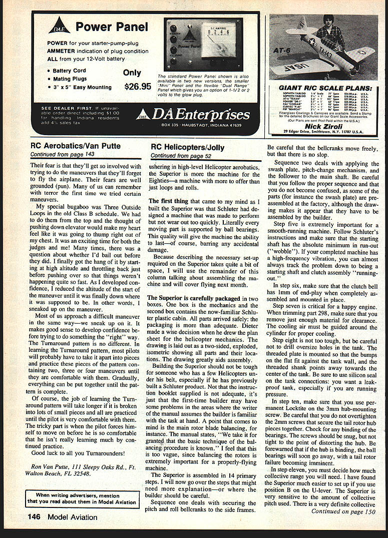
- Use permanent Loctite on the 3 mm hub-mounting screw. Do not overtighten the 2 mm screws that seat the rotor hub pieces together. Check for any binding of the bearings. The screws should be snug but not so tight that they distort the hub. If the hub is binding, the ball bearings will soon fail, with a tail rotor failure becoming imminent.
- Step eleven: collective range and U-lever position.
- Decide how much collective range you will need. I have found the Superior much easier to set up if you use position B on the U-lever. The Superior is very sensitive to the amount of collective pitch used. There is a very definite collective range, and attempting to fly the rotor out of this range can cause over-revving or lugging of the system, depending on whether you are using too much positive or negative pitch at the wrong throttle setting.
Following the rest of the manual should see your Superior assembled without any problems.
Final notes and safety
Next month, we will cover final set-up and flying of the Superior.
Until next month, if you are flying one of the new helicopter radios fitted with an invert-flight switch, be careful. We had an incident where a fellow club flier was hovering and reached up to flip the aileron dual-rate. He hit the invert switch instead, and a broken machine was the result. If you are not using the invert switch, check to see if you can deactivate it on the control board of your transmitter. If not, a good idea from Ed Baxter is to drop an appropriate-size wheel collar over the offending switch to lock it in place.
Keep those cards and letters coming (as well as the photos and questions).
Larry Jolly 5501 W. Como Santa Ana, CA 92703
Transcribed from original scans by AI. Minor OCR errors may remain.

