
RADIO CONTROL JETS
Jim Hiller, 6090 Downs Road, Champion, OH 44481
I'm stepping in for Del Ellis while he tends to a health problem. I wish him a speedy and healthy recovery.
Golden West — the Hammer turbine
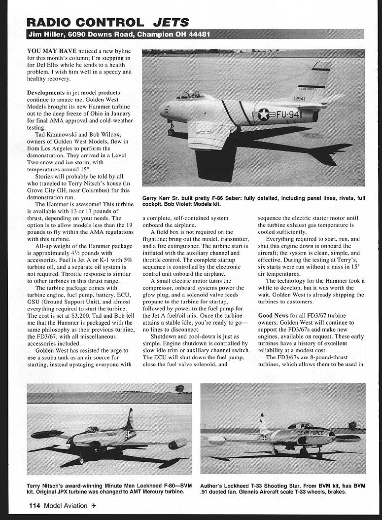
Developments in jet model products continue to amaze me. Golden West Models brought its new Hammer turbine out to the deep freeze of Ohio in January for final AMA approval and cold-weather testing. Tad Krzanowski and Bob Wilcox, owners of Golden West Models, flew in from Los Angeles to perform the demonstration. They arrived during a Level Two snow-and-ice storm, with temperatures around 15°F.
Stories will probably be told by all who traveled to Terry Nitsch's house in Grove City, OH (near Columbus) for this demonstration run.
The Hammer is impressive. This turbine is available with either 13 or 17 pounds of thrust to suit different model and AMA-regulation needs. The all-up weight of the Hammer package is approximately 4½ pounds with accessories. Fuel is Jet A or K-1 with 5% turbine oil; a separate oil system is not required. Throttle response is similar to other turbines in this thrust range.
The turbine package includes:
- Turbine engine
- Fuel pump
- Battery
- ECU (electronic control unit)
- GSU (Ground Support Unit)
- Almost everything required to start the turbine
Cost is set at $3,200. Tad and Bob tell me the Hammer is packaged with the same philosophy as their previous FD3/67 turbine, with miscellaneous accessories included.
Golden West resisted using a scuba tank as a start-air source and instead put a complete, self-contained starting system onboard the airplane. A field box is not required on the flightline — bring the model, transmitter, and a fire extinguisher. The turbine start is initiated with the auxiliary channel and throttle control; the ECU onboard controls the complete startup sequence.
Typical start sequence:
- A small electric motor turns the compressor.
- Onboard systems power the glow plug.
- A solenoid valve feeds propane for startup.
- The fuel pump is then powered for the Jet A/oil mix.
- Once the turbine attains a stable idle, the engine is ready — no external lines to disconnect.
Shutdown and cool-down are equally simple. Engine shutdown is controlled by slow idle trim or an auxiliary channel switch. The ECU will:
- Shut down the fuel pump,
- Close the fuel-valve solenoid,
- Sequence the electric starter motor until turbine exhaust temperature is sufficiently cooled.
Everything required to start, run, and shut the engine down is onboard the aircraft. The system is clean, simple, and effective. During testing at Terry’s, six starts were run without a miss in 15°F air.
Golden West is already shipping Hammers to customers.
FD3/67 support
Good news for FD3/67 owners: Golden West will continue to support the FD3/67s and make new engines available on request. These early turbines have a history of excellent reliability at modest cost.
The FD3/67s are 8-pound-thrust turbines and fit many earlier ducted-fan models with only modest airframe changes. I flew my FD3/67 for years in a CSM Exterminator. I’ve seen the turbine in many different 0.72–0.90 cu in ducted-fan models, all performing well within the available power range.
Delta proof-of-concept — leading-edge yaw control
After testing the Hammer, our group watched the first-flight videotape of Golden West’s latest commissioned model: a 30-pound, Hammer-powered delta with leading-edge devices for yaw control.
This aircraft is a proof-of-concept model exploring an alternative yaw-control method for aircraft without a fin and rudder. A series of small air bags is arranged along the leading edge; these bags are inflated on one side to create additional drag and thus produce a yaw moment.
The delta’s flight performance and handling looked good. The yaw effect from inflating the leading-edge devices showed potential, though it was not very effective in this early form. One reason for using a turbine on this model was to eliminate torque effects. The purpose of the model is to study the control concept for potential use on future stealth-type aircraft.
Wheel brakes — why you should consider them
One popular option for high-performance ducted-fan and turbine models is wheel brakes. If you haven’t tried them, do so. I’ve flown brake-equipped models for several years and miss the brakes when flying an unbraked model.
Benefits:
- Highly effective when taxiing and preparing for takeoff
- Reduce landing roll — especially useful for dead-stick landings on short runways
Most brake systems for ducted-fan and turbine models are well-developed and include brake calipers, wheel hubs, and hard tires. Hard tires are required for reasonable life on paved surfaces; normal tires wear quickly under braking stress.
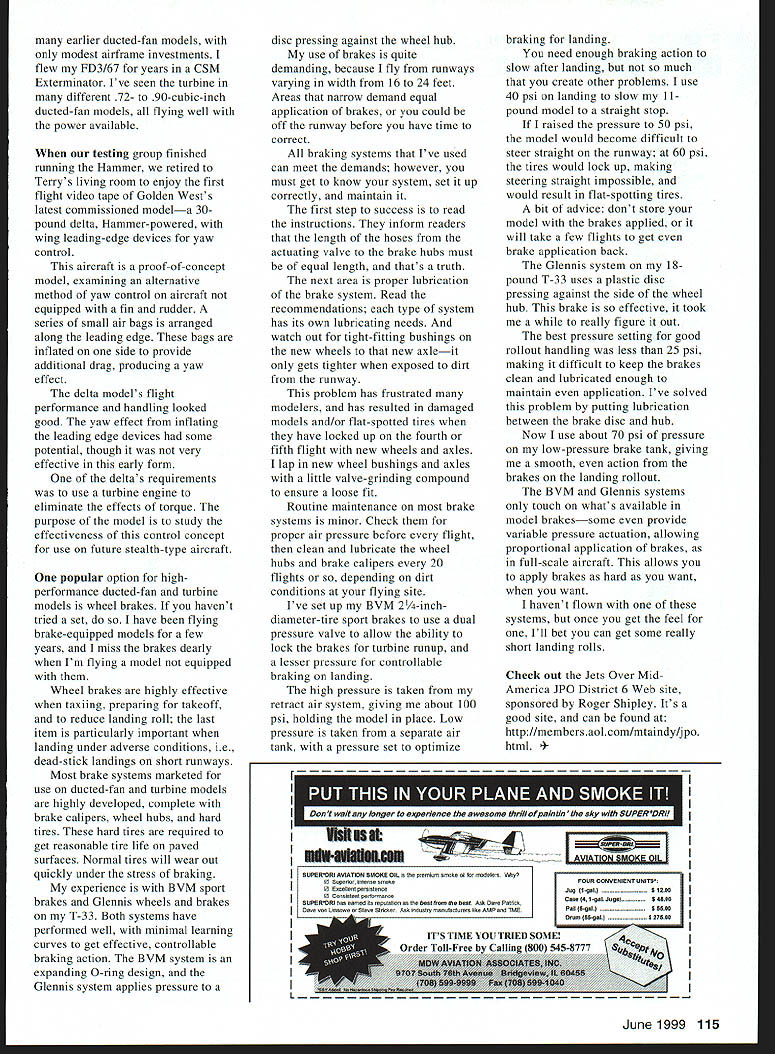
My experience is with BVM sport brakes and Glennis wheels-and-brakes on my T-33. Both systems have performed well with minimal learning curves. The BVM system is an expanding O-ring design; the Glennis system applies pressure to a disc pressing against the wheel hub.
I fly from runways varying in width from 16 to 24 feet. Narrow areas demand equal application of brakes, or you can be off the runway before you correct. All braking systems I’ve used can meet these demands, but you must learn your system, set it up correctly, and maintain it.
Setup, maintenance, and practical tips
Key setup and maintenance points:
- Read the instructions. They emphasize that the length of hoses from the actuating valve to the brake hubs must be equal — and that’s true.
- Lubricate per manufacturer recommendations; each system has specific needs.
- Watch for tight-fitting bushings on new wheels and axles. Dirt can tighten the fit further. I lap new wheel bushings and axles with a little valve-grinding compound to ensure a loose fit and avoid lockups that can cause damaged models or flat-spotted tires on early flights.
Routine maintenance is minor:
- Check brake air pressure before every flight.
- Clean and lubricate wheel hubs and brake calipers every ~20 flights or more often in dirty conditions.
Pressure setup examples from my aircraft:
- My BVM 2-1/4-inch-diameter-tire sport brakes use a dual-pressure valve:
- High pressure (from retract air system) ~100 psi to lock brakes for turbine runup.
- Low pressure (separate tank) set for landing braking — I use about 40 psi to stop my 11-pound model in a straight line.
- At 50 psi the model becomes difficult to steer; at 60 psi tires will lock and flat-spot.
- Advice: don’t store your model with brakes applied — it can take several flights to get even brake application back.
- The Glennis system on my 18-pound T-33 uses a plastic disc pressing against the wheel hub. It’s very effective; best runway handling was achieved below 25 psi, but keeping the brakes clean and lubricated to maintain even application was difficult at that level. I solved this by adding lubrication between the brake disc and hub and now use about 70 psi on my low-pressure brake tank for smooth, even action on landing rollout.
Many systems provide variable-pressure actuation for proportional braking similar to full-scale aircraft. Once you get the feel for one system, you can achieve very short landing rolls.
Resources
Check out the Jets Over Mid-America (JPO District 6) web site, sponsored by Roger Shipley: http://members.aol.com/mtaindy/jpo.html
Transcribed from original scans by AI. Minor OCR errors may remain.

