
RADIO CONTROL JETS
Jim Hiller — 6090 Downs Road, Champion, OH 44481
Top Gun Scale Meet
Jets are alive and well in scale competition. I went to West Palm Beach, Florida for the Top Gun Scale meet, and the jets were out in force. Terry Nitsch led the way in the awards category. Check out the results in the September Top Gun article.
The models flown in competition were beautiful works of art; it was almost a shame to risk them by flying them, but they were flown. Those competing with jet models put on a great display.
Top Gun is held on a grass polo field lined with trees, so it isn't a place for the faint of heart. The ducted-fan modelers had to be careful in the wet morning grass; the extra drag made the takeoffs longer.
The pilots handled the job in a very professional manner, with decision points set in advance of the takeoff. The pilots adhered to these decision points and shut down when required, accepting a flight attempt as the cost of saving the model so it could fly later. All pilots could learn from these guys; they know how to save their models.
Turbines and Notable Models
Turbines at Top Gun represented the full spectrum of manufacturers. I saw numerous AMIs, RAMs (RA Microjets), Sophias, and the new Golden West Hammer. All turbines performed well in competition, showing how far technology has come in just a few years. There's definitely a selection of quality turbines to choose from when we make turbine purchases.
Among the noteworthy examples was Jack Diaz's awesome AMI-powered BVM (Bob Violett Models) F-4 — a truly impressive setup flown by a professional, quality pilot.
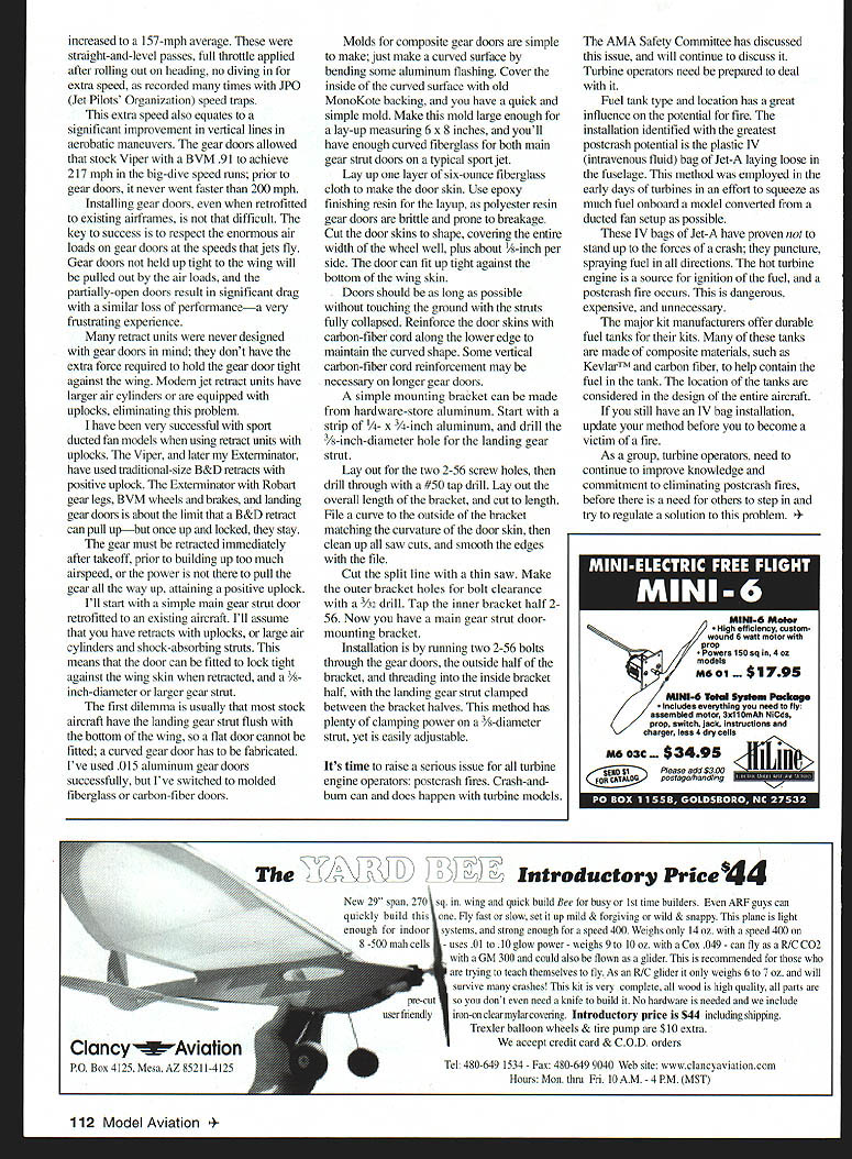
Quite a few MiG-15s were in competition, powered mainly by RAM turbines. Dave Ribbe's MiG-15 was powered by the new Sophia, proving the flexibility of the airframe to handle various turbine installations.
Tad Krzanowski and I competed in Team Scale with his incredible MiG-17; this model epitomizes jet scale modeling. It is an original-design, all-composite aircraft loaded with all of the neat options one could imagine. The model is equipped with flaps, speed brakes, shock-absorbing landing gear of Tad's own design, full-sequencing gear doors, proportional brakes, and a Golden West Hammer turbine with onboard starting capabilities. Tad selected a very forgiving airfoil that sets up easily on final for landing—not a given on a highly swept-wing design.
From initiation of turbine startup to completion of the flight, all is controlled from the transmitter — a totally awesome experience. The more I've flown this model, the more I've learned to get the most from all of the features, such as learning to use the proportional brakes to control taxi speed. Controlling a jet's taxi speed is a chore—especially in grass, where it takes a great deal of power just to start moving. Once the jet starts moving, I have to back off the throttle and hope I've got about right for a nice taxi speed. I use the brake control as I would use the brakes on a car: depress slowly, only as much as I need.
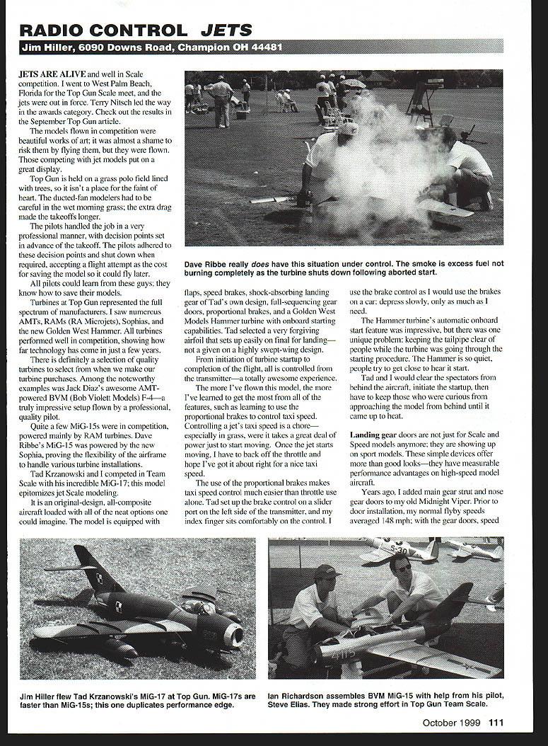
The Hammer turbine's automatic onboard start feature was impressive, but there was one unique problem: keeping the tailpipe clear of people while the turbine was going through the starting procedure. The Hammer is so quiet, people try to get close to hear it start. Tad would clear spectators behind the aircraft, initiate the startup, then have to keep those who were curious until it came up to heat.
Gear Doors: Performance and Benefits
Landing gear doors are not just for scale and speed models anymore; they are showing up on sport models. These simple devices offer more than good looks — they have measurable performance advantages on high-speed model aircraft.
Years ago, I added main gear strut and nose gear doors to my old Midnight Viper. Prior to door installation, my normal flyby speeds averaged 148 mph; with the gear doors, speed increased to a 157-mph average. These were straight-and-level passes, with full throttle applied after rolling out on heading, no diving in for extra speed, as recorded many times with JPO (Jet Pilots' Organization) speed traps.
This extra speed also equates to a significant improvement in vertical lines in aerobatic maneuvers. The gear doors allowed that stock Viper with a BVM .91 to achieve 217 mph in the big-dive speed runs; prior to gear doors, it never went faster than 200 mph.
Installing gear doors, even when retrofitted to existing airframes, is not that difficult. The key to success is to respect the enormous air loads on gear doors at the speeds that jets fly. Gear doors not held up tight to the wing will be pulled out by the air loads, and the partially-open doors result in significant drag with a corresponding loss of performance — a very frustrating experience.
Many retract units were never designed with gear doors in mind; they don't have the extra force required to hold the gear door tight against the wing. Modern jet retract units have larger air cylinders or are equipped with uplocks, eliminating this problem.
I have been very successful with sport ducted-fan models when using retract units with uplocks. The Viper, and later my Exterminator, have used traditional-size B&D retracts with positive uplock. The Exterminator with Robart gear legs, BVM wheels and brakes, and landing gear doors is about the limit that a B&D retract can pull up — but once up and locked, they stay.
The gear must be retracted immediately after takeoff, prior to building up too much airspeed, or the power is not there to pull the gear all the way up and attain a positive uplock.
Retrofitting a Main Gear Strut Door
I'll describe a simple main gear strut door retrofitted to an existing aircraft. I'll assume you have retracts with uplocks, or large air cylinders and shock-absorbing struts. This means the door can be fitted to lock tight against the wing skin when retracted, and the 1-inch-diameter or larger gear strut.
The first dilemma is that most stock aircraft have the landing gear strut flush with the bottom of the wing, so a flat door cannot be fitted; a curved gear door has to be fabricated. I've used .015-inch aluminum gear doors successfully, but I've switched to molded fiberglass or carbon-fiber doors.
Molds for composite gear doors are simple to make; just make a curved surface by bending some aluminum flashing. Cover the inside of the curved surface with old MonoKote backing, and you have a quick and simple mold. Make this mold large enough for a lay-up measuring 6 x 8 inches, and you'll have enough curved fiberglass for both main gear strut doors on a typical sport jet.
Lay up one layer of 6-ounce fiberglass cloth to make the door skin. Use epoxy for the finishing resin for the layup, as polyester resin gear doors are brittle and prone to breakage. Cut the door skins to shape, covering the entire width of the wheel well, plus about 3/8 inch per side. The door can fit up tight against the bottom of the wing skin.
Doors should be as long as possible without touching the ground with the struts fully collapsed. Reinforce the door skins with carbon-fiber cloth at the lower edge to maintain the curved shape. Some vertical carbon-fiber rod reinforcement may be necessary on longer gear doors.
A simple mounting bracket can be made from hardware-store aluminum:
- Start with a strip of 1/4 x 3/4-inch aluminum, and drill a 5/16-inch-diameter hole for the landing gear strut.
- Lay out for the two 2-56 screw holes, then drill through with a #50 tap drill.
- Lay out the overall length of the bracket, and cut to length.
- File a curve to the outside of the bracket matching the curvature of the door skin, then clean up all saw cuts, and smooth the edges with a file.
- Cut the split line with a thin saw. Make the outer bracket holes for bolt clearance with a 3/32-inch drill. Tap the inner bracket half 2-56.
Now you have a main gear strut door-mounting bracket.
Installation is by running two 2-56 bolts through the gear doors, the outside half of the bracket, and threading into the inside bracket half, with the landing gear strut clamped between the bracket halves. This method has plenty of clamping power on a 3/8-inch-diameter strut, yet it is easily adjustable.
Safety: Postcrash Fires
It's time to raise a serious issue for all turbine engine operators: postcrash fires. Crash-and-burn can and does happen with turbine models. The AMA Safety Committee has discussed this issue and will continue to discuss it. Turbine operators need to be prepared to deal with it.
Fuel tank type and location have a great influence on the potential for fire. The installation identified with the greatest postcrash potential is the plastic IV (intravenous fluids) type fuel tank — a Jet-A bag laying loose in the fuselage. This method was employed in the early days of turbines in an effort to squeeze as much fuel onboard a model converted from a ducted-fan setup as possible.
These IV bags of Jet-A have proven not to stand up to the forces of a crash; they puncture, spraying fuel in all directions. The hot turbine engine is a source for ignition of the fuel, and a postcrash fire occurs. This is dangerous, expensive, and unnecessary.
The major kit manufacturers offer durable fuel tanks for their kits. Many of these tanks are made of composite materials, such as Kevlar™ and carbon fiber, to help contain the fuel in the tank. The location of the tanks is considered in the design of the entire aircraft.
If you still have an IV bag installation, update your method before you become a victim of a fire. As a group, turbine operators need to continue to improve knowledge and commitment to eliminating postcrash fires, before there is a need for others to step in and try to regulate a solution to this problem.
Transcribed from original scans by AI. Minor OCR errors may remain.

