
Radio Control: Old Timers
Dee B. Mathews
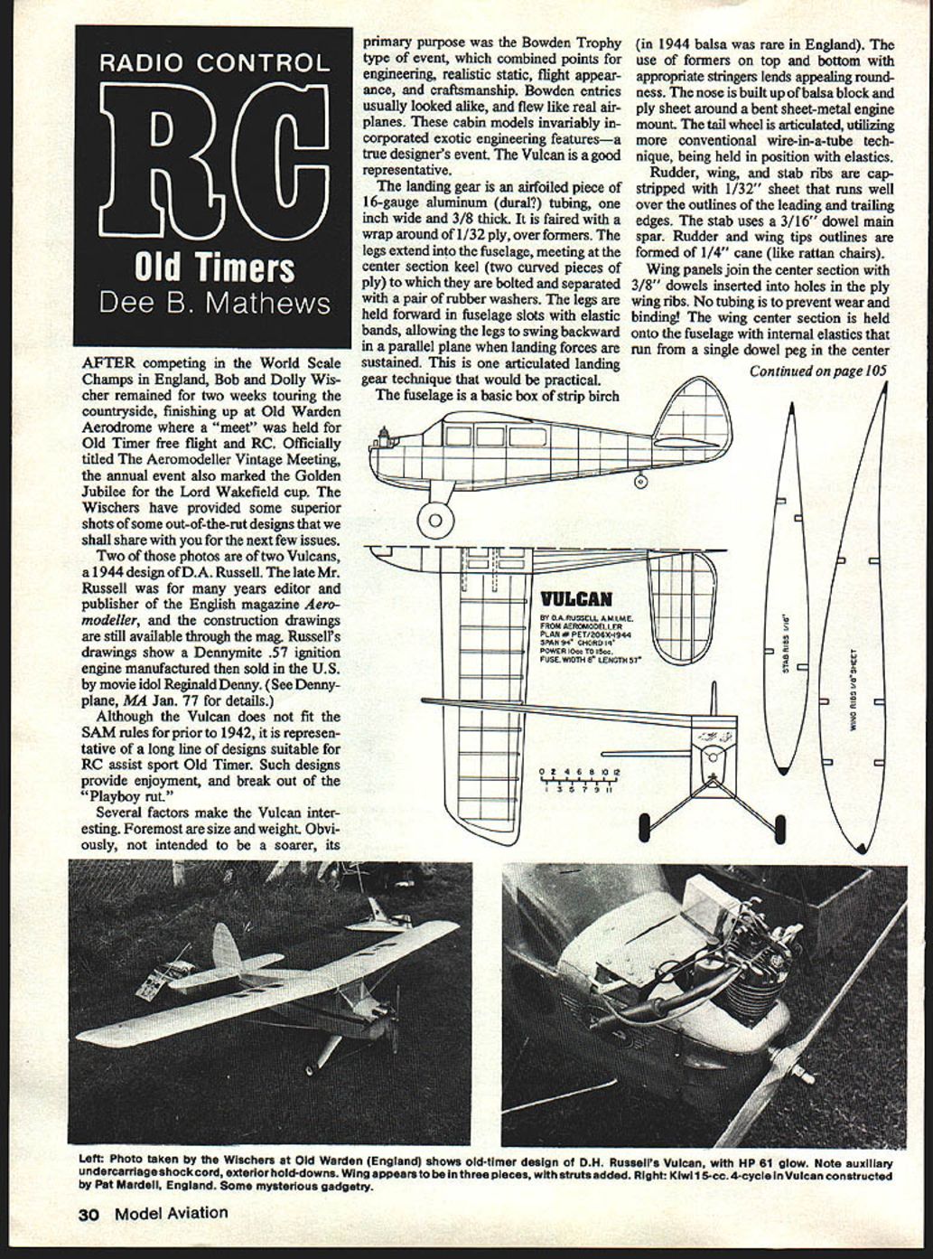
After competing in the World Scale Champs in England, Bob and Dolly Wischer remained two weeks touring the countryside, finishing up at Old Warden Aerodrome where a meet was held for Old Timer free flight and RC. Officially titled the Aeromodeller Vintage Meeting, the annual event also marked the Golden Jubilee of the Lord Wakefield Cup. The Wischers provided excellent photos of some out-of-the-rut designs; two of those photos are of two Vulcans, a 1944 design by D.A. Russell. The late Mr. Russell was for many years editor and publisher of the English magazine Aeromodeller, and construction drawings are still available through the magazine. Russell’s drawings show the Dennymite .57 ignition engine, manufactured and sold in the U.S. by Reginald Denny (see “Dennyplane,” MA Jan. ’77 for details).
Although the Vulcan does not fit the SAM rules for pre‑1942 designs (it is a 1944 design), it is representative of a long line of cabin designs suitable for RC‑assist sport Old Timer flying. Such designs provide enjoyable flying and break out of the “Playboy” rut.
Why the Vulcan is interesting
Several factors make the Vulcan notable, foremost its size and weight and its design intent. The Vulcan was primarily a Bowden Trophy–type airplane, where judging combined engineering, realistic static appearance, flight characteristics, and craftsmanship. Bowden entries usually looked like real airplanes and flew like them; cabin models of this type often incorporated exotic engineering features — a true designer’s event. The Vulcan is a good representative of that tradition.
Landing gear
- Main gear: an airfoiled piece of 16‑gauge aluminum (duralumin?) tubing, about 1" wide and 3/8" thick.
- The gear is faired with a wrap of 1/32" plywood over formers.
- Legs extend into the fuselage and meet at the center‑section keel (two curved pieces of ply) to which they are bolted, separated by a pair of rubber washers.
- The legs are held forward in fuselage slots with elastic bands, allowing them to swing backward in a parallel plane under landing forces — an articulated landing gear technique that is practical and effective.
Fuselage and tail
- The fuselage is basic box construction of strip birch (balsa was scarce in England in 1944). Formers on top and bottom with appropriate stringers give a pleasing roundness.
- The nose is built up from balsa block and ply sheet around a bent sheet‑metal engine mount.
- Tailwheel is articulated using the conventional wire‑in‑a‑tube technique and is held in position with elastics.
Wings and control surfaces
- Rudder, wing, and stab ribs are cap‑stripped with 1/32" sheet that runs well over the outlines of the leading and trailing edges.
- The stabilizer uses a 3/16" dowel main spar.
- Rudder and wing tip outlines are formed from 1/4" cane (similar to rattan chair cane).
- Wing panels join the center section with 3/8" dowels inserted into holes in the ply wing ribs; the original design used no tubing to prevent wear and binding.
- The wing center section is held to the fuselage with internal elastics that run from a single dowel peg in the wing center to a similar peg inside the fuselage.
Gusset technique
Russell’s drawings show a gusset method that may be surprising: gussets running between the wing rib and trailing edge are cut from 1/8" square balsa strips (not sheet). They are set at a 45° angle and cemented only at their ends — an efficient, lightweight method of reinforcing the junction.
RC conversion and recommended modifications
The Vulcan adapts well to RC conversion:
- Empennage hinge points are obvious and the cabin provides adequate access for radio equipment.
- Recommended power: a 9–10 cc glow unit for the standard size.
- For smaller installations consider scaling to about 70% for a 3–4 cc powerplant.
Construction and fitting recommendations:
- Use laminated basswood for the tip outlines.
- Fit music‑wire wing pins running in appropriately sized brass tubing to reduce wear and binding at the wing center.
- Although a one‑piece wing is possible, measure doors and car trunks — you may prefer folding or multi‑piece wings for transport.
- Consider improving the wing and stab hold‑down method from Russell’s original design; the photo illustrations suggest more satisfactory alternatives.
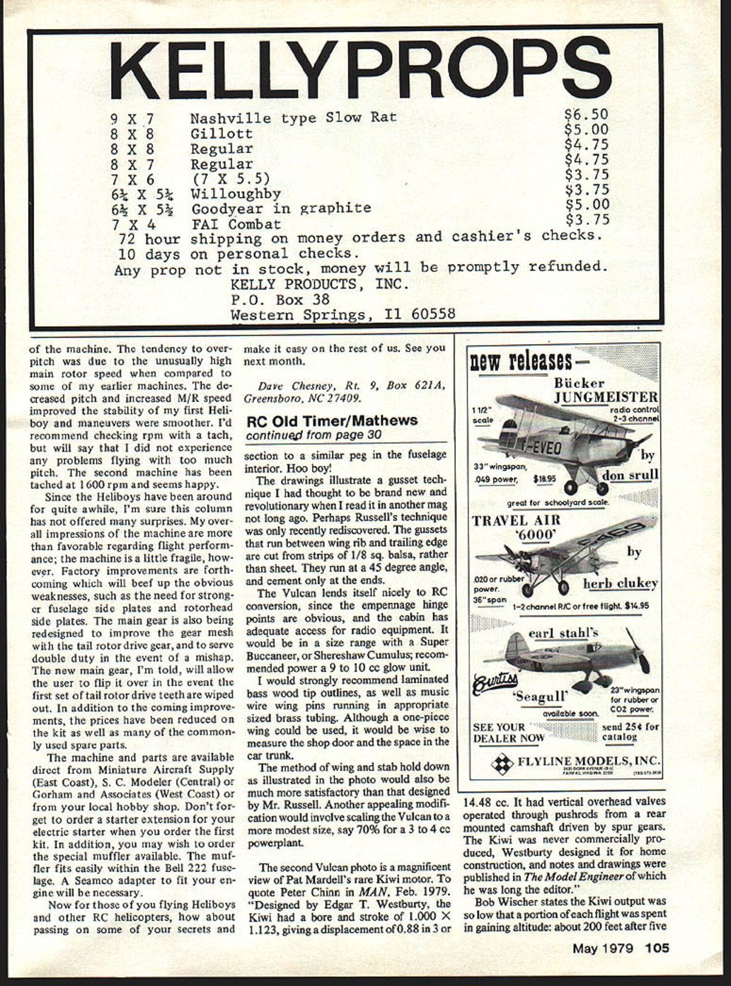
The Kiwi motor (photo subject)
One of the photos shows Pat Mardell’s rare Kiwi motor. Quoting Peter Chinn (MA, Feb. 1979): “Designed by Edgar T. Westbury, the Kiwi had a bore and stroke of 1.000 x 1.123, giving a displacement of 0.88 in³ or 14.48 cc. It had vertical overhead valves operated through pushrods from a rear‑mounted camshaft driven by spur gears. The Kiwi was never commercially produced; Westbury designed it for his own construction, and notes and drawings were published in The Model Engineer, of which he was long the editor.”
Bob Wischer noted the Kiwi’s output was so low that a portion of each flight was spent in regaining altitude — about 200 feet after five minutes.
Notes: construction drawings for Russell’s Vulcan remain available from Aeromodeller. Photographs and construction detail are useful references for builders considering a faithful rebuild or an RC conversion.
Transcribed from original scans by AI. Minor OCR errors may remain.

