
Radio Control
Old-Timers
Dr. D. B. Mathews
SPARKERS!
In my June column, I mentioned the availability of replacement parts — including the ignition timers ("points") — for those old spark-ignition engines which have been lying around for years, unused. Also, it seems to me that every issue of this magazine contains new ads for reproductions of various old ignition-type power plants. Therefore, it seems obvious that many RC-assist fliers are going to have ignition engines to fly for the first time in their modeling experiences.
Since first exposure to model airplane ignition systems can bring on a case of "anxieties" in some modelers, I've asked Bill Schmidt (who lives here in Wichita, KS) to share the nuts-and-bolts aspects of operating sparkers, since he has a vast range of experience with them and has been most successful in obtaining maximum power from the engines. Here, then, is guest columnist Bill Schmidt:
Schmidt's Sparker Spectrum
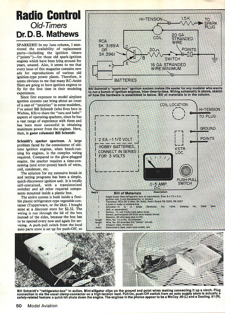
A large problem faced by the connoisseur of old-time ignition engines is the complex wiring required when bench-running engines. Compared to the glow-plugged engine, the sparker requires a time-consuming (and error-prone) batch of wires, coil, condenser, etc.
The solution for my extensive break-in and testing programs has been a simple, quick-disconnect ignition unit. It is totally self-contained, with a transistorized switcher and all other required components mounted inside a plastic box.
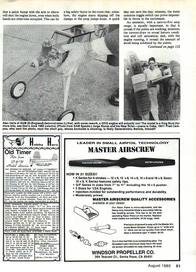
The entire system is built inside a flexible plastic refrigerator-type vegetable container (Tupperware, or the like). I bought mine at a discount store for $2.32. The wiring is run through the lid of the box instead of the sides, because the box has to be opened every now and again for servicing. A push-pull switch from the local auto parts store is set up for push-OFF, so plug connection is via the usual clamp-connector on a high-tension lead. The pull-ON, push-OFF switch from an auto supply store is actually a safety-related feature; a quick hit shuts down the engine when both hands are otherwise occupied. In the event some engine starts slipping off the clamps or the prop jumps loose, a quick slap can save the day, whereas a common toggle switch can prove impossible to throw in the excitement.
An ammeter (zero-to-five amp range) is equally important; it reveals points working, monitors current draw, shows battery condition and coil saturation while the engine is running, and indicates the amount of dwell being exhibited by the points.
Dwell is a term seldom mentioned in the old articles and books on the subject, and it is something of a mystery to most modelers — even the true old-timers who ran these things when they were the only game in town. Dwell is defined as the length of time the points are closed during 360° of crankshaft rotation. Normally, dwell is between 90° and 130°. Too little dwell, and the coil is not saturated long enough to deliver a strong spark; too much, and the plane's on-board ignition battery pack will be drained excessively. Successful operation of miniature model ignition engines depends on the degree of dwell, just as it does in your automobile or lawn mower engines.
High-speed racing engines (McCoy, Dooling, etc.) that turn over 10,000 rpm can use dwells of over 120° and not draw excessive current; however, lower-rpm engines should be set in the range of 95° to 110°. The ammeter should show that the battery current, while the engine is running, is about 1/2 amp (or less). If the current is more than that (dwell is set too long), the model's on-board battery pack won't last long.
When using my "quick box," I merely clamp my favorite old sparker engine to it and use a universal mount, slide the box behind it, and clip the three alligator-clip-equipped wires to the appropriate places:
- Minus to ground (preferably right to a handy spot on the engine)
- Plus to the pointed lead
- High-tension lead to the spark plug
It's ready to fire up! The wiring diagram, parts list and parts sources should enable anyone to construct this extremely handy device.
Tips for Using the "Quick Box"
Look at the circuit and notice that the coil is always connected to the batteries. Not to fear — not a bit of current will flow until the transistor's base connection is tickled. The 20-ohm resistor limits the current across the points to 60–70 mA, so the batteries will last a very long time.
The wiring must be at least 16-gauge stranded wire, except for the lead from the transistor base to the ignition points. A current of four amps flows everywhere in the system, except for the "tickler" circuit to the points, and the tickler circuit can easily be handled by 20-gauge wire. So, you see that a very hot spark can be generated.
I also fly this circuit in my models, using two Ni-Cd batteries in place of the glow-plug batteries in my "quick box." I use a knife-switch made from brass shim stock on the plane. Be sure all connections are well-soldered with resin-core solder (never use acid-core solder in electrical circuits). The cardinal error committed by modelers over 50 years of ignition flying has been to skimp on wire size and to have poor solder connections. Remember that we're only dealing with four amps at 2½ or 3 volts here — a mere 10 or 12 watts — so there's not much heat available. It takes only a little bit of resistance in the ignition circuit to reduce efficiency and performance in a hurry.
The outstanding feature of this circuit is that the primary circuit is soldered closed permanently, and there is no switch in the circuit to fail or cause resistance.
Troubleshooting Hints
- Check the ignition coil for electrical continuity from its primary to its secondary. A good coil will show about 3,500 to 4,700 ohms of resistance. A spark coil that is open (broken wire, etc.) will still spark — until the engine is in compression.
- Since the circuit I'm using has no condenser, that little troublemaker is no longer a threat. However, for RC use, put a 1,000 to 10,000 ohm resistor in the high-tension lead at the spark-plug end. This will help suppress RF interference. The resistor must be at the plug end of the lead to do any good. Use the least amount of resistance possible.
- You can experiment with RF suppression by turning on the RC receiver and shorting the ignition system's timer lead to ground with a small screwdriver while watching the plane's control surfaces for glitches.
I fly both a Futaba and a Canon radio and have never had any need for shielding anything in the model. I do try to keep the coil and ignition module forward and away from the radio equipment. This includes the battery, which has been found to pick up RF interference when using a H Electronics CD electronic ignition system in the plane — Doc.
The coil will not function if any metal is near it. Always mount it with wood or plastic clamps.
Finally, Doc Mathews and I discovered, last time out, that the clamp-type battery boxes we used back then don't work very well anymore. The batteries should be held with elastics if you're using one of those boxes. Better still, solder the battery tabs into the circuit and stuff the batteries inside.
That's the end of Bill's guest article.
About the Author
Bill Schmidt makes a living designing and installing remote-monitoring and controlling equipment for municipal water systems and the like. He was employed by Minneapolis Honeywell for many years — and he claims that he got the job because he took along his homemade Berkeley Aerotrol system, and it so impressed the interviewer that they hired him on the spot. Bill is so into restoring and collecting antique sparker engines that he has even begun making piston rings for them.
D. B. Mathews 8420 Nantucket, Wichita, KS 67212
Transcribed from original scans by AI. Minor OCR errors may remain.

