
Radio Control: Pylon Racing
Bill Hager 4 Holly Springs Dr. Conroe, TX 77302
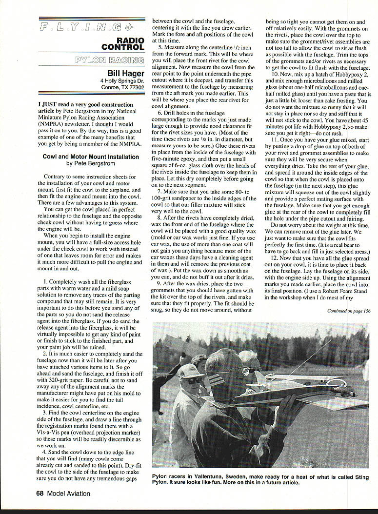
I just read a very good construction article by Pete Bergstrom in my National Miniature Pylon Racing Association (NMPRA) newsletter. I thought I would pass it on to you. By the way, this is a good example of one of the many benefits that you get by being a member of the NMPRA.
Cowl and Motor Mount Installation
by Pete Bergstrom
Contrary to some instruction sheets for the installation of your cowl and motor mount, first fit the cowl to the airplane, and then fit the engine and mount into the cowl. There are a few advantages to this system. You can get the cowl placed in perfect relationship to the fuselage and the opposite cheek cowl without having to guess where the engine will be.
When you begin to install the engine mount, you will have a full-size access hole under the cheek cowl to work with instead of one that leaves room for error and makes it much more difficult to pull the engine and mount in and out.
- Completely wash all the fiberglass parts with warm water and a mild soap solution to remove any traces of the parting compound that may still remain. It is very important to do this before you sand any of the parts so you do not sand the release agent into the fiberglass. If you do sand the release agent into the fiberglass, it will be virtually impossible to get any kind of paint or finish to stick to the finished part, and your paint job will be ruined.
- It is much easier to completely sand the fuselage now than it will be later after you have attached various items to it. So go ahead and sand the fuselage, and finish it off with 320-grit paper. Be careful not to sand away any of the alignment marks the manufacturer might have put on his mold to make it easier for you to find the tail incidence, cowl centerline, etc.
- Find the cowl centerline on the engine side of the fuselage, and draw a line through the registration marks found there with a Vis-a-Vis pen (overhead projection marker) so these marks will be readily discernible as we work on.
- Sand the cowl down to the edge line that you will find (many cowls come already cut and sanded to this point). Dry-fit the cowl to the side of the fuselage to make sure you do not have any tremendous gaps between the cowl and the fuselage, centering it with the line you drew earlier. Mark the fore and aft positions of the cowl at this time.
- Measure along the centerline 1/2 inch from the forward mark. This will be where you will place the front rivet for the cowl alignment. Now measure the cowl from the rear point to the point underneath the pipe cutout where it is deepest, and transfer this measurement to the fuselage by measuring from the aft mark you made earlier. This will be where you place the rear rivet for cowl alignment.
- Drill holes in the fuselage corresponding to the marks you just made large enough to provide good clearance for the rivet sizes you have. (Most of the time the rivets are 1/8 in. in diameter, but measure yours to be sure.) Glue these rivets in place from the inside of the fuselage with five-minute epoxy, and then put a small square of 6-oz. glass cloth over the heads of the rivets inside the fuselage to keep them in place. Let this dry completely before going on to the next segment.
- Make sure that you take some 80-100-grit sandpaper to the inside edges of the cowl so that the filler mixture will stick very well to the cowl.
- After the rivets have completely dried, wax the front end of the fuselage that the cowl will be placed on with a good quality wax (mold or car wax works just fine). If you use car wax, the use of more than one coat will not gain you anything because most of the car waxes these days have a cleaning agent in them and will remove the previous coat of wax. Put the wax down as smooth as you can, and do not buff it out after it dries.
- After the wax dries, place the two grommets that you should have gotten in the kit over the top of the rivets, and make sure that they fit properly. The fit should be snug, so that they do not move around, without being so tight you cannot get them on and off relatively easily. With the grommets on the rivets, place the cowl over the top to make sure the grommet/rivet assemblies are not too tall to allow the cowl to sit as flush as possible with the fuselage. Trim the tops of the grommets and/or rivets as necessary to get the cowl to fit flush with the fuselage.
- Now, mix up a batch of Hobbypoxy 2, and mix enough microballoons and milled glass (about one-half microballoons and one-half milled glass) until you have a paste that is just a little bit looser than cake frosting. You do not want the mixture so runny that it will not stay in place nor so dry and stiff that it will not stick to the cowl. You have about 45 minutes pot life with Hobbypoxy 2, so make sure you get it right—do not rush.
- Once you have your glue mixed, start by putting a drop of glue on top of both your rivet and grommet assemblies to make sure they will be very secure when everything dries. Take the rest of your glue, and spread it around the inside edges of the cowl so that when the cowl is placed on the fuselage this glue mixture will squeeze out of the cowl slightly and provide a mating surface with the fuselage. Make sure you get enough glue at the rear of the cowl to completely fill the hole under the pipe cutout and fairing. Don't worry about the weight at this time. We can remove most of the glue later. We want to make sure the cowl fits perfectly the first time (and it is a real bear to have to go back and fill in just selected areas).
- Now that you have all the glue spread out on your cowl, it's time to place it back on the fuselage. Lay the fuselage on its side, with the engine side up. Using the alignment marks you made earlier, place the cowl into its final position. (I use a Robart Foam Stand in the workshop when I do most of my fuselage work. It makes it real easy to rotate the fuselage to any position I desire, and with rubber bands across the top, it will stay in those positions as long as you want it to.)
Once the cowl is in the position you want it (look real close from all angles to make sure you get this right!), tape the cowl into position with masking tape, and allow this whole assembly to dry for 24 hours.
- After the cowl assembly has dried completely, you now have to remove it. If you simply try to pry it off or pull it off, it probably will not release from the fuselage. What you should do is simply start pressing on the fuselage in the area around the cowl to pop the fuselage loose from the cowl. The cowl will always be a lot stiffer than the fuselage, so the fuselage skin will move first. Carefully continue doing this all the way around the cowl until it has completely released itself from the fuselage.
Once this is done, you should be able to simply pull the cowl straight up and off the fuselage along the cowl vertical axis of the rivets. Congratulations; you now have a perfectly fitted cowl (but it does not look like much yet—hold on).
- With a sanding block and some 120-grit paper, smooth out all the excess glue on the outside of the cowl. You will have to remove any extra that made it to the outside surface of the fairing and sandpaper just wrapped around your fingers or hand to fit the curves of the cowl. When I am finished, I only have a fine line of glue between the original cowl line and the new line that fits the fuselage. There should not be a great amount of filler anywhere on your cowl if you did the job right.
- With a Dremel tool and sanding drum, remove most of the material on the inside of the cowl. When you are working on the back of the cowl around the pipe cutout, do not remove any material directly under the cutout (i.e., the front of the pipe fairing). By leaving material here, you will create an air dam and prevent air from entering the area under the pipe fairing. What is more, this air will want to lift off the cowl from the fuselage in flight. (It is one of the sources of some of the buzzing you hear on certain airplanes, with the back part of the cowl constantly being lifted and dropped back onto the fuselage.) Immediately behind this air dam you created, you can remove as much material as you would like. Just remember to leave enough material so that the grommet is secure in its mounting. After you have done all this sanding, remove the cowl to the fuselage and admire your handiwork—a perfectly fitted cowl (and now it looks like one!).
- At this time, remove the cowl, and with some acetone remove any traces of wax from the mating surfaces.
- Replace the cowl on the front end, and with a Vis-a-Vis pen, draw the outline of the cowl on the front of the fuselage. This will help us with a guide for the engine access hole. Remove the cowl, and measure from the front of the fuselage back 4-3/8 in. and draw a line that is parallel to the front nose ring. This is the guideline for the back side of the cutout. Now draw a line measuring between 1/8 in. and 1/4 in. inside the outer cowl outline. This will be the line you will cut to when removing material for your engine access hole.
To cut this hole out, Dremel makes a 1/8-in. rounded-tip carbide bit that is absolutely great for cutting fiberglass parts. Starting somewhere in the middle of the outline, go ahead and rough cut this area out of the front of the fuselage. While you still have this tool in place, rough cut the area of the spinner ring after you have sanded the parting line flush with the fuselage. (If you sand after you cut the spinner ring, you stand a good chance of changing the designer's thrust line because you are working with much less material and it is removed much easier.) Cut this opening now so the engine has someplace to go when we try to place it in the fuselage. Remember, do not remove any area around the front alignment rivet!
Now, put your trusty sanding drum back on your Dremel, and sand the cutouts you just made to a pleasing outline within the confines of the guidelines you drew earlier. Do the spinner ring at the same time. On the spinner ring, I usually leave between 1/8 in. and 3/16 in. on the outside edges.
- Let's mount the engine and firewall now. The first thing you need to do is take an old spinner backplate, and glue a 1/32-in. plywood ring to the back of it. I say a ring because you want the thrust washer from the engine to be in contact with the back of the spinner plate, not the plywood ring. I usually mount this with some medium CyA (cyanoacrylate glue), and I have one spinner I use just for this purpose so I do not have to remove it. (After you have been racing for a while, you will ruin the nose cone portion of quite a few spinners and will have plenty of backplates to use. If you are using a new spinner, just spot glue this ring to the back—the plywood will remove easily enough with an X-Acto knife.)
- At this time, place the motor mount into the fuselage either through the cutout you made or through the wing saddle, and then bolt your engine to it through the engine access cutout. Make sure you wipe the mounting flats of the engine mount free of balsa and fiberglass pieces so that the engine sits flush with the rails. If you do not, you will be putting unwanted thrust offset into your engine mounting alignment. Once the engine is securely bolted to the engine mount, mount your spinner backplate, cutoff prop (a mistake from the prop carving floor!), washer, and nut so this whole assembly is one solid piece.
- Next, we want to fit the firewall into place so that it is snug but does not distort the fuselage sides in any way. The best way that I have found is by setting my bench disk sander to about a five-degree angle, and going around the outside edges of the firewall. Important to note: Make sure that you use the back of the firewall as your guide, not the front.
- With the engine/spinner combination flush with the fuselage spinner plate, place the firewall into position from the wing cut so that it fits flush with the back of the engine mount. Take extra care at this point to make sure that it is truly flush and that the firewall does not distort the fuselage in any way. Use a long-handled screwdriver through the wing cutout to gently tap the firewall into place flush with the engine mount. Because you have already fitted your cowl, you can now use it as an alignment guide for the head of the engine by placing it onto the rivets and making sure the engine is centered inside the cowl. (You may want to wrap a couple of layers of masking tape around the engine to get a snug fit into the cowl so you know where it goes.) When you are satisfied with this alignment, drop some medium CyA in about four different places around the engine mount/firewall joint, and allow it to dry.
- Once the CyA has dried, remove the spinner and then the engine from the engine mount, and put both of these aside for a moment. Now you want to remove the firewall/engine mount assembly from the fuselage so you can install blind nuts to hold the mount in place. Generally, you will not be able to remove this assembly in one piece through the engine cutout or the wing cutout, so go ahead and pop the engine mount loose from the firewall while it is still in the fuselage.
Because the CyA does not stick very well to your engine mount, after you have removed the engine mount you will find glue spots that will show you exactly where the engine mount was on the firewall before you removed it. We will use these as a guide when placing the engine mount on the firewall to drill our mounting holes.
- With the engine mount and the firewall removed from the fuselage, relocate the mount on the firewall and mark the positions for your mounting bolts to go through the firewall. When drilling these holes, use a 3/32-in. bit from the front (assuming you are using a 6-32 mounting bolt), and then from the backside, drill in 1/4 in. with a 3/16-in. drill bit to provide relief for the blind mounting nuts (T-nuts) you will be using. Without this relief, you will find it difficult to mount the T-nuts and will take a chance on splitting the wood and distorting the threads in the nuts.
Once these holes are drilled, press the mounting nuts into place on the back of the firewall, and use some medium CyA around their edges to secure them in place. Be careful not to get any CyA on the inside of the threads, or you will have to replace those nuts! Now, with a sanding block remove the glue flashing from the front of the firewall that we used for our mount alignment.
- Place the firewall back inside the fuselage from the wing cutout, and bolt the engine mount to it from the front. Once you have these two pieces together, remount the engine and spinner assembly onto the engine mount. Before we go any further, double-check the alignment with the head of the bore (the plywood ring on the back of the spinner should still be in place). At this time, double-check your alignment of the engine head with the cowl.
- Once you are satisfied with your alignment, tack glue the firewall to the fuselage with a couple of drops of medium CyA, and let this assembly dry. Once the assembly is dry, remove the spinner, engine, and mount from the airplane, leaving only the firewall in place. Now mix up a slurry of Hobbypoxy 2 and milled glass, and working from the front of the firewall, work in the glue mixture as best you can around and between the firewall and fuselage. Remember not to be too rough so you do not break the spot-glue joints that hold the firewall in place.
Finish off the front of the firewall by leaving a small glue fillet around the entire firewall edge, and let this assembly cure overnight with the cowl in place on the fuselage, pointed up in the air. Note—be careful not to leave any extra glue where the engine mount will be bolted so you still have a nice, smooth and flat surface.
- Once the fillets have dried on the front of the firewall, do the same procedure with Hobbypoxy 2 and milled glass on the back of the firewall. These steps should not take a lot of glue. A huge fillet on either side of the firewall adds no strength but a tremendous amount of weight. Do not be stingy, but remember you are not building this airplane to withstand a 180-mph crash, either!
- Once the firewall is secure in the fuselage and the glue is dry, it is time to remount the engine mount. Mix up a small batch of five-minute epoxy, and spread it onto the firewall just prior to bolting the firewall in place. This will not only provide the glue proofing for the firewall, but it will also provide a hard, smooth surface for the engine mount to be bolted to when it is dry. Important: bolt the engine mount in place while the glue is still wet, not afterward, because then you will not have any idea what kind of thrust line you have.
- I like to have the front of my engine mounts secured to the fuselage as well. If you are using a Nelson mount, the mounting holes and screws come with the mount and all you need to do is make a hold-down mount from 1/8-in. plywood that fits the inside outline of the Nelson mount and will fit well with the inside contour of your fuselage. (Make sure that this mounting plate just barely touches the inside of the fuselage so you do not distort the fuselage or the motor mount when it is in place.)
Once you have accomplished this, bolt the 1/8-in. plywood plate to the engine mount, and then glue the plate to the fuselage with Hobbypoxy 2 and milled glass. If you are using a Stenberg motor mount or another brand that has no hold-on holes already provided, you will have to drill and tap the front of your motor mount to provide for these. Use 6-32 screws for this; drill and tap accordingly.
You will also have to make two mounting plates—one for each side—because these other motor mounts do not extend far enough forward to clear the bottom of the engine case. Again make your plates and mount them to the engine mount before you glue them in place so they fit the mount and you are not forcing the mount to fit the plates and possibly distorting the whole assembly. Remember—the more solid and straight the mounting installation, the more power you will get out of your engine.
- If you are running a Nelson or an O.S. engine, you will have to enlarge the cowls of most kits to get them to fit around the heads. (Hopefully, the manufacturers are working hard to solve this problem, because they were made to fit an ST case and head.)
If you do need to enlarge the cowl, I have a relatively painless way that I'll tell you about. With the engine mounted in the fuselage, try to mount the cowl. Make cutouts on either side of the cowl to fit your engine installation. This may take a while, because you want to remove only as much material as you need to, not a whole lot more. Once the cowl fits in the fuselage satisfactorily with the engine in place, make sure you have at least 1/16 in. of clearance around the cutouts you just made so that air may pass between your modification and the engine case and head.
- Remove the cowl, and wrap the engine head and case with about four layers of masking tape. On top of this masking tape, secure some Saran Wrap (use this brand; it works the best on everything we will talk about in this article), so that the glue will not stick to the engine or the tape. Now cut a couple of swatches of 6-oz. cloth that are big enough to cover the hole(s) that you made for the enlargement. What we are going to do is use the engine for an inside mold of the enlargement we need.
- Once you have your fiberglass pieces cut out, mix up some more Hobbypoxy 2, with no filler for right now. Soak the fiberglass pieces with the epoxy resin, and wrap them around the exposed engine head. After you have the fiberglass on the engine head, go ahead and remount the cowl, being careful that you do not displace the fiberglass around the head. Once the cowl is seated on the fuselage, carefully work with the cloth so that it is in contact with the inside of the cowl, and let this assembly set up for about three hours. In that time, it will have firmed up but not be completely hard.
- Now mix up a batch of Hobbypoxy 2 and microballoons into a fairly thick paste. This will be used as a filler on the outside of your enlargements. Go ahead and put this slurry mixture on over the top of the fiberglass cloth, making sure that you have plenty of material to sand after this dries. Do not be too shy here; otherwise it may take a couple of nights to get enough material on there to make it look good. Let this dry overnight, and then remove the cowl from the airplane. Remove the tape and Saran Wrap from the engine, and then replace the cowl on the fuselage. It should fit just fine now, with the only thing left to do being to sand the outside of the cowl so it has a pleasing appearance and only a slight bulge over the original.
Congratulations, you should now have a front end that fits well, is aligned great, and looks perfect.
Do you want the inside scoop on more stories like this, along with being a member of the organization that is responsible for all that we have in Pylon Racing today? Here's how you can join the NMPRA:
- Send name, address, phone number, AMA number, and interest (F-1, QM, Q500, FAI) to:
Ron Short 5224 Teasdale North Hollywood, CA 91607
- Include dues:
- $15 for a nonflying membership
- $30 for a flying membership
- $33 outside the U.S.
See you next month
Transcribed from original scans by AI. Minor OCR errors may remain.

