
RADIO CONTROL PYLON RACING
Bill Hager, 4 Holly Springs Dr., Conroe TX 77302
Here is a report from Lou Rodriguez about the Formula One race in Las Vegas on March 25–26, 1995:
The LVRC did a great job of hosting this event. A freshly sodded football field was used for the pit area. It was like a big picnic on the grass.
The racing was tremendous, with some new pilots doing a fantastic job. Larry Drury, Tom Hart, and Delbert Godon made good showings with low times and smooth flying.
The greatest excitement was saved for last with the Gold, Silver, and Bronze Calcutta races. Darrol Cady squeaked out a narrow victory in the Bronze race. The Silver race had several lead changes throughout. Travis Flynn and Rich Tocci battled the whole race. Rich appeared to be ahead at the finish but a cut was his demise and Travis claimed the victory.
The Gold race will be remembered for a long time and gave everyone watching quite a thrill. Richard Verano, Chip Hyde, Bill Hager, and Henry Bartle put on a display of formation flying never seen before. All four airplanes were wingtip to wingtip for the entire race. The four shutters at Pylon One closed as one every lap. A small fishnet would have covered all the airplanes at any point on the race course. Remarkably, there was no midair.
Richard was rewarded with the checkered flag and some extra spending money. Race fans were rewarded with a spectacle. This race will be billed next year as "The Gambler National Formula One Race". You will definitely want to be there if you are interested in Formula One racing.
F1 Expert
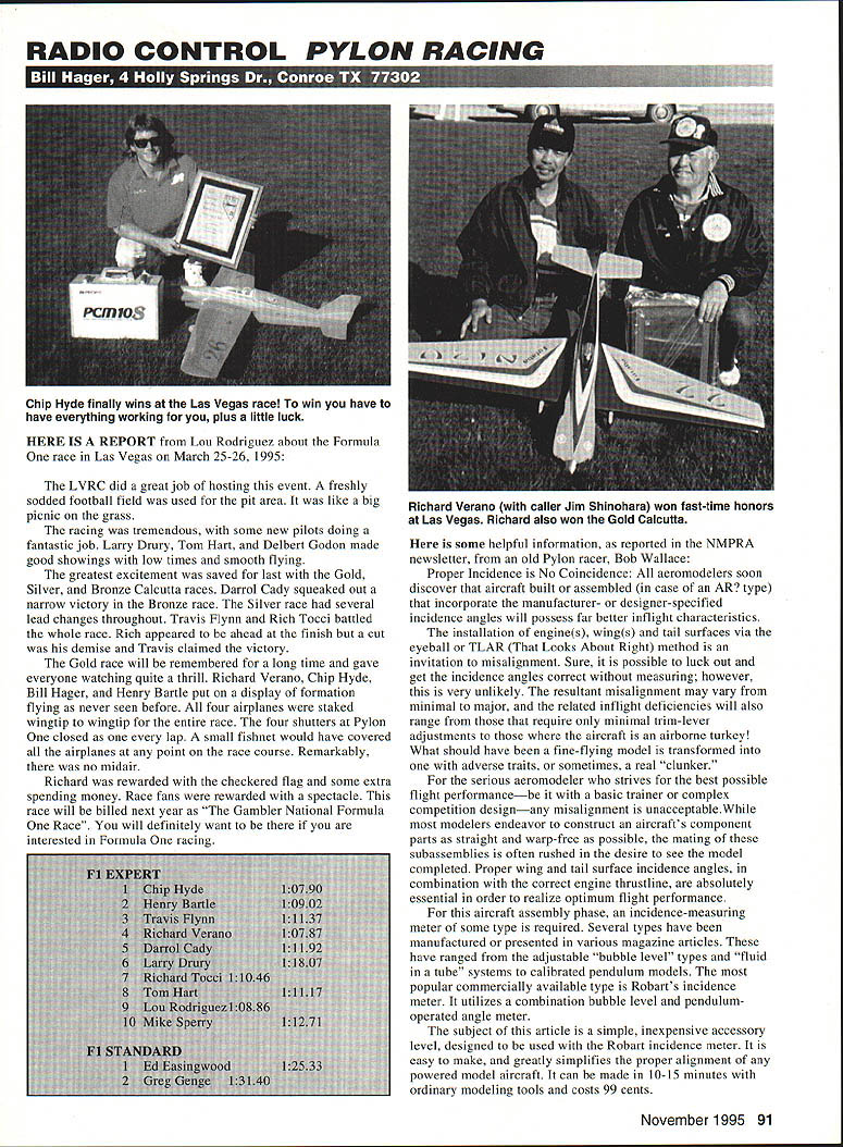
- 1 Chip Hyde — 1:07.90
- 2 Henry Bartle — 1:09.02
- 3 Travis Flynn — 1:11.37
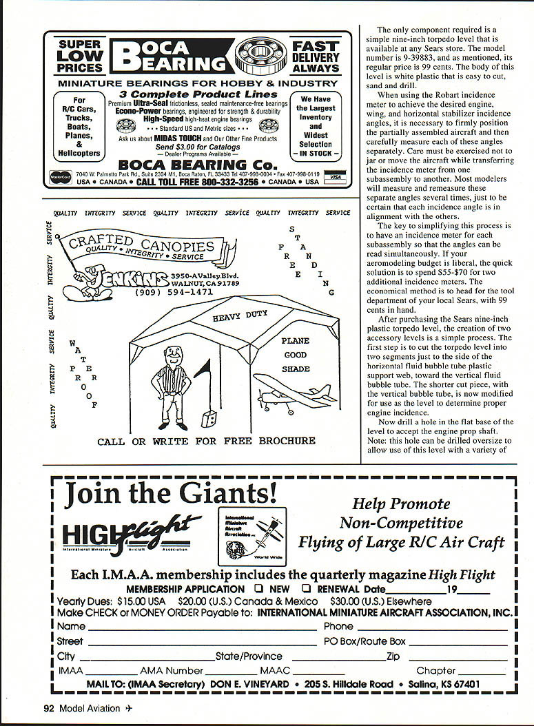
- 4 Richard Verano — 1:07.87
- 5 Darrol Cady — 1:11.92
- 6 Larry Drury — 1:18.07
- 7 Richard Tocci — 1:10.46
- 8 Tom Hart — 1:11.17
- 9 Lou Rodriguez — 1:08.86
- 10 Mike Sperry — 1:12.71
F1 Standard
- 1 Ed Easingwood — 1:25.33
- 2 Greg Genge — 1:51.40
Here is some helpful information, as reported in the NMPRA newsletter, from an old pylon racer, Bob Wallace:
Proper Incidence No Coincidence
All aeromodelers soon discover that aircraft built or assembled (in the case of an AR type) that incorporate the manufacturer- or designer-specified incidence angles will possess far better inflight characteristics.
The installation of engine(s), wing(s), and tail surfaces via the eyeball or TLAR (That Looks About Right) method is an invitation to misalignment. Sure, it is possible to luck out and get the incidence angles correct without measuring; however, this is very unlikely. The resultant misalignment may vary from minimal to major, and the related inflight deficiencies will also range from those that require only minimal trim-lever adjustments to those where the aircraft is an airborne turkey!
What should have been a fine-flying model is transformed into one with adverse traits, or sometimes, a real "clunker."
For the serious aeromodeler who strives for the best possible flight performance—be it with a basic trainer or complex competition design—any misalignment is unacceptable. While most modelers endeavor to construct an aircraft's component parts as straight and warp-free as possible, the mating of these subassemblies is often rushed in the desire to see the model completed. Proper wing and tail surface incidence angles, in combination with the correct engine thrustline, are absolutely essential in order to realize optimum flight performance.
For this aircraft assembly phase, an incidence-measuring meter of some type is required. Several types have been manufactured or presented in various magazine articles. These have ranged from the adjustable "bubble level" types and "fluid in a tube" systems to calibrated pendulum models. The most popular commercially available type is Robart's incidence meter. It utilizes a combination bubble level and pendulum-operated angle meter.
The subject of this article is a simple, inexpensive accessory level, designed to be used with the Robart incidence meter. It is easy to make, and greatly simplifies the proper alignment of any powered model aircraft. It can be made in 10–15 minutes with ordinary modeling tools and costs 99 cents.
A component required is a simple nine-inch torpedo level available at Sears, store model number 9-39883. I mention its regular price, 99 cents. The body level is white plastic and is easy to cut, sand, and drill. Using the Robart incidence meter, achieve the desired engine, wing, and horizontal stabilizer incidence angles. It is necessary to firmly position the partially assembled aircraft and carefully measure the angles separately. Care must be exercised so the jarred aircraft does not move when transferring the incidence meter subassembly to another position.
Most modelers will measure and remeasure the separate angles several times just to be certain of the incidence angle alignment. One of the key simplifying processes is to have the incidence meter subassembly such that angles can be read simultaneously. If your aeromodeling budget is liberal, a quick solution is to spend $55–$70 for two additional incidence meters. An economical method is to head for the tool department of your local Sears, with 99 cents in hand.
After purchasing the Sears nine-inch plastic torpedo level, the creation of two accessory levels is a simple process. The first step is to cut the torpedo level into two segments just to the side of the horizontal fluid bubble tube plastic support web, toward the vertical fluid bubble tube. The shorter cut piece, with the vertical bubble tube, is now modified for use as the level to determine proper engine incidence.
Now drill a hole in the flat base of the level to accept the engine prop shaft. Note: this hole can be drilled oversize to allow use of this level with a variety of prop shaft diameters and engine sizes. Mine was drilled at 2 1/4 so that it would fit engine shafts up to 3/16. The flat base of this level is 5/8 wide, so it could be drilled to fit even the larger gasoline-powered engines. The sharp edges of this level portion are then radiused and sanded smooth.
The longer portion of the original nine-inch level can be used to determine the correct alignment of the horizontal stabilizer.
In most cases, the easiest method of aligning an aircraft is to use the wing as a fixed base and adjust the engine/firewall and horizontal stabilizer to it. While the engine and stabilizer levels discussed in this article are not adjustable, it is a simple matter to align the engine or stabilizer to incidence angles that differ from that of the wing.
- For example, if three degrees of negative engine incidence (downthrust) is specified, and the wing incidence is zero degrees, position the aircraft so that the wing-mounted Robart incidence meter indicates three degrees of positive incidence. The level mounted on the engine should then indicate that it is level to produce the desired three degrees of negative incidence. The same method can be employed to install the horizontal stabilizer with either positive or negative incidence.
As with almost every tool or construction aid, the levels described do have limitations. The stabilizer level cannot be used on an airfoiled surface and, with both being nonadjustable, the main incidence meter mounted onto the wing must be used to produce related angles. However, for 99 cents and a few minutes of work, you can have two very handy aircraft tools that will simplify the very important alignment phase.
The NMPRA represents all pylon racers. Tips like this are found in the monthly newsletter. Why not join? For more information write to Dave Doyle, 133 Shannon Dr., Warwick RI 02889; or better yet, send:
- $15 — non-flying membership
- $30 — flying membership
- $33 — outside the U.S. membership
Transcribed from original scans by AI. Minor OCR errors may remain.

