
RADIO CONTROL PYLON RACING
Robert Dible 4408 A Enterprise Place, Fremont CA 94538
Do you want to race?
There are many types of competition to satisfy the urge, from club events to FAI (Fédération Aéronautique Internationale). For the novice racer, networking with experienced competitors is important: find out what events are held in your area (or within travel distance) and attend a race. Keep in mind that as the event increases in difficulty and cost, the distance you must travel to a contest often increases. Even if your goal is Giant Scale or Formula One, start with a Quickie-based event to learn the fundamentals at low cost.
The learning curve in pylon racing is easy to start, but becomes more challenging as speeds increase. Find your comfort level and learn new skills to achieve your goal.
Most successful racers did not get there alone; pylon racing is a team sport. Speed helps, but flying ability and someone to race with matter more.
Objective of this column
My objective is to provide a wide variety of information, demystify "speed secrets," and help develop a growing racing community. Because speed is one element of racing, I'll examine airframe design features and which design choices are better than others. Popularity of a design often has more to do with who campaigns it successfully than how good it is—or a design wins more often simply because more people fly it.
Design and Drag
Main design criterion
The chief design criterion for any racing aircraft is drag reduction. This is especially true in formula events, where engine size and certain design aspects are restricted. For a fixed amount of delivered horsepower, drag determines speed in flight. Propeller selection is critical for transferring engine power to thrust and can make or break performance; that topic will be examined separately.
There are two main types of drag an aircraft has: parasite drag and induced drag.
Parasite drag
Parasite drag consists of skin friction, form drag, and interference drag at junctions between wing, fuselage, tail, etc. The designer's job is to develop a clean airframe. Methods to reduce parasite drag include:
- Reduce surface area where possible. Wing area is usually fixed by the event formula, but fuselage and tail surfaces can often be optimized.
- Use a pod-and-boom fuselage concept (as in sailplanes) to achieve nearly laminar flow on the pod while the boom has diminished turbulent surface area. This concept can be adapted for Quickies.
- Move the widest part of the fuselage back toward the wing trailing edge. This helps prevent separation and reduces interference drag between wing and fuselage, producing an effect similar to a wing fillet.
- Shape the fuselage aft of the wing as a pressure-recovery area (similar to a NACA duct): have the fuselage expand forward to promote laminar flow and bow inward behind the wing to recover turbulent energy and reduce surface area (see Fig. 1). Jon Sharp’s full-scale Formula 1 Nemesis exhibits these features. (See three-view at http://www.ddg.com/Nemesis/.)
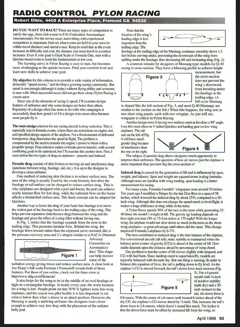
- Place the wing appropriately in the fuselage cross-section. A midwing in an oval fuselage or a high wing on a rectangular fuselage can be beneficial; in many cases the worst location is low. The P-51 Mustang is effectively a near-midwing design, with careful fuselage shaping and radiator placement that prevent wing downwash from spilling under the fuselage (Fig. 2).
- Avoid poor cross-section scaling. Many Mustang-type Q-40 models copy a full-scale profile for height measurement but fail to prevent downwash from breaking under the fuselage at the wing trailing edge; this can make the wing act as two short panels (see Fig. 3). Wingspan is critical in pylon racing.
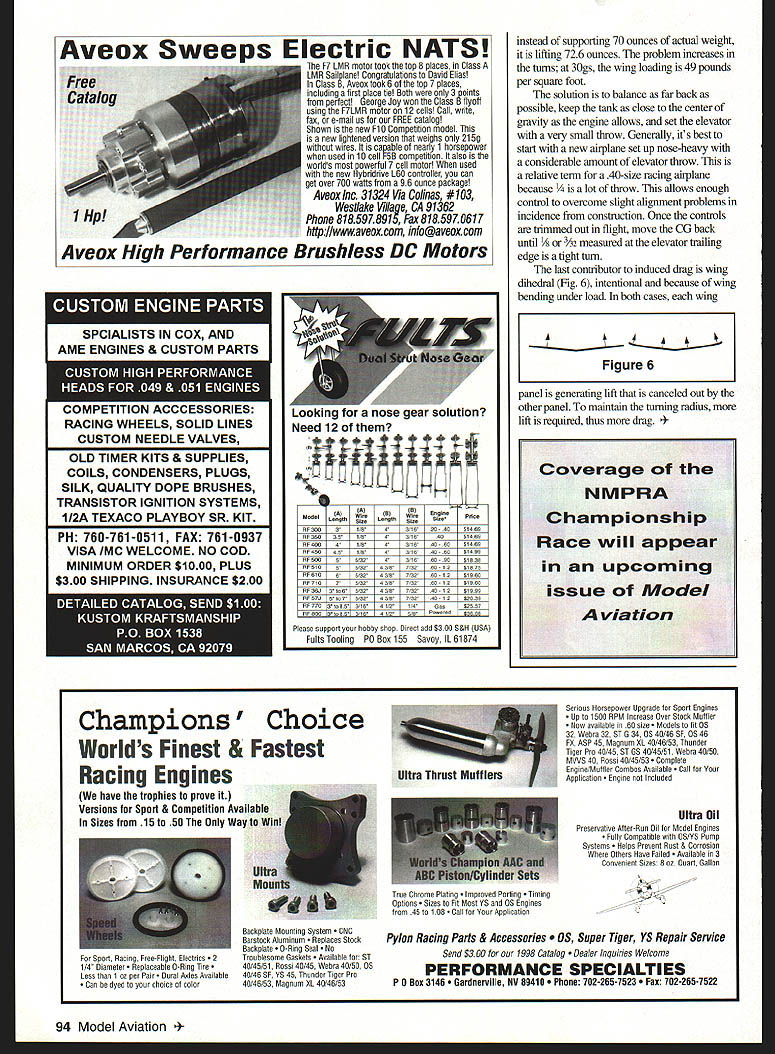
- Avoid junctions where two surfaces meet at less than a 90° angle. Such intersections—seen on some V-tailed Quickies or poorly faired landing gear—generate significant interference drag (see Fig. 4).
- Keep landing gear low, short, and well faired on low-wing airplanes to minimize interference drag.
The question is how air moves past the airplane, not just how big the cross-section is.
Induced drag
Induced drag is caused by lift generation and is influenced by span, weight, and balance. Span and weight enter drag formulas as squared terms. While wing loading is familiar, span loading is a better measurement for racing.
- Wingspan and span loading: Historically, many Formula 1 models had wingspans around 50 inches. Increasing span can greatly reduce induced drag—example: modifying a Stinger to 58 inches lowered induced drag by about 25% versus a 50-inch wing. This change made a substantial difference in turn performance and improved Formula 1 airplanes by roughly 6–7%.
- Turns: A pylon racer spends about 30% of a race in the turns while generating 25–40 times the model’s weight in lift. G-loading depends on how tight you turn (50–75 foot radius at high speeds). A longer wing helps the airplane retain speed in turns compared to short-wing designs.
Contributors to induced drag include:
- Trim balance (CG and fuel effects)
- For conventional tail-aft aircraft, static stability requires the center of gravity (CG) to be ahead of the center of lift. How stable the airplane is depends on that forward distance (usually measured as percent of chord).
- The center of lift moves slightly with airspeed; the CG moves with fuel burn. Models are typically balanced with the tank dry so landings match takeoffs, but fuel shifts can significantly change tail loading. Example calculation: for a 4 lb model with 1/4" positive stability (tank dry) and a 20" moment to the tail, the tail downforce is 0.8 oz. If a 6 oz fuel tank is located 6" ahead of the dry CG, the CG moves forward 3/8", increasing tail downforce to 2.6 oz. That extra downforce must be offset by increased wing lift—so instead of supporting 70 oz of actual weight, the wing supports 72.6 oz. Under high G's (e.g., 30 G), wing loading increases dramatically (example: 49 lb/ft²).
- Solutions:
- Balance as far back as safely possible.
- Keep the tank as close to the CG as engine installation allows.
- Set elevator travel to a very small throw.
- Typical setup approach: start with a new airplane nose-heavy with considerable elevator throw for control during trimming. Once alignment and controls are trimmed in flight, move the CG back until 1/8" to 3/32" measured at the elevator trailing edge produces a tight turn.
- Wing dihedral (intentional dihedral or dihedral introduced by wing bending under load)
- In both cases, each wing panel’s lift has a component canceled by the other panel, requiring more total lift to maintain the same turning radius, which increases induced drag (see Fig. 6).
Practical setup tips
- Start with a conservative, nose-heavy setup and adequate elevator throw to compensate for minor construction misalignments.
- Trim controls in flight, then back the CG up in small increments toward the recommended tight-turn measurement (1/8" to 3/32" at elevator trailing edge).
- Locate the fuel tank as close to the CG as possible to minimize CG shift as fuel is burned.
- Minimize interference drag by fairing junctions properly, avoiding shallow-angle intersections, and keeping landing gear short and well faired.
Figures referenced:
- Fig. 1: Fuselage expansion forward to trailing edge and pressure‑recovery shaping aft of wing.
- Fig. 2: Mustang fuselage trailing edge continuing smoothly aft to prevent downwash spillage.
- Fig. 3: Full-scale Mustang versus typical Q‑40 Mustang cross‑sections.
- Fig. 4: Effect of junction angle on interference drag.
- Fig. 5: Tail downforce changes with CG/fuel position.
- Fig. 6: Dihedral and wing bending effects on induced drag.
Transcribed from original scans by AI. Minor OCR errors may remain.

