
RADIO CONTROL PYLON RACING
Duane Gall, 1267 S. Beeler Court, Denver, CO 80231
I got some pictures again this month. That's the good news. The bad news is I had to supply them myself. Some folks have a face for radio; I have photographic skills made for writing.
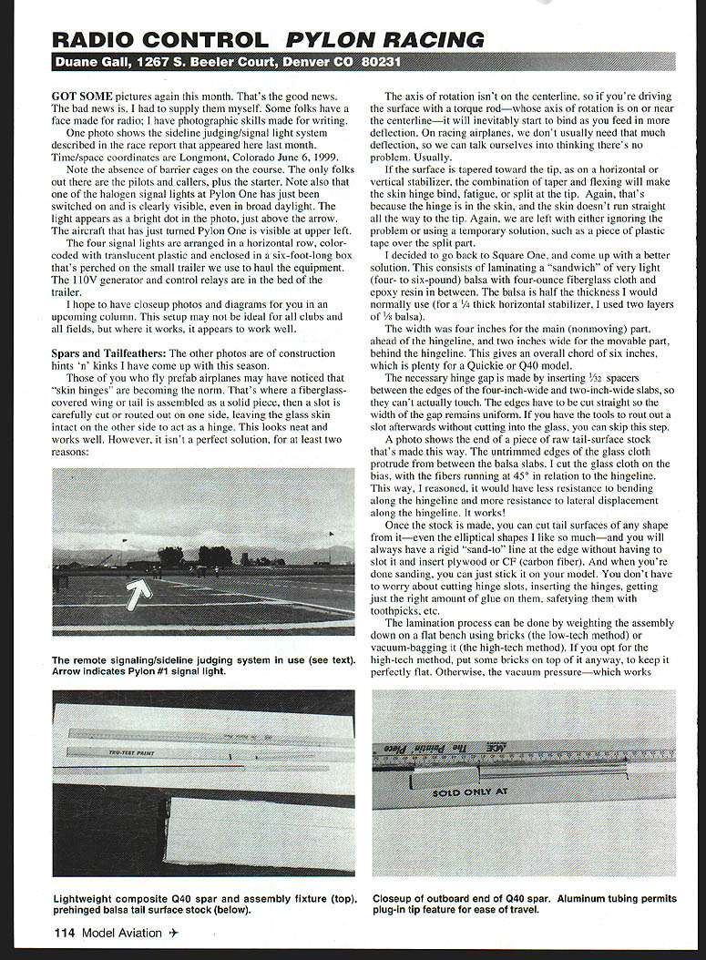
One photo shows the sideline judging/signal-light system described in the race report that appeared here last month.
Time/space coordinates: Longmont, Colorado, June 6, 1999.
Note the absence of barrier cages on the course. The only folks out there are the pilots and callers, plus the starter. Note also that one of the halogen signal lights at Pylon One has just been switched on and is clearly visible, even in broad daylight. The light appears as a bright dot in the photo, just above the arrow. The aircraft that has just turned Pylon One is visible at upper left.
The four signal lights are arranged in a horizontal row, color-coded with translucent plastic and enclosed in a six-foot-long box that's perched on the small trailer we use to haul the equipment. The 110-volt generator and control relays are in the bed of the trailer.
I hope to have closeup photos and diagrams for you in an upcoming column. This setup may not be ideal for all clubs and all fields, but where it works, it appears to work well.
Spars and Tailfeathers
The other photos are of construction hints 'n' kinks I have come up with this season.
Those of you who fly prefab airplanes may have noticed that "skin hinges" are becoming the norm. That's where a fiberglass-covered wing or tail is assembled as a solid piece, then a slot is carefully cut or routed out on one side, leaving the glass skin intact on the other side to act as a hinge. This looks neat and works well. However, it isn't a perfect solution, for at least two reasons:
- The axis of rotation isn't on the centerline, so if you're driving the surface with a torque rod—whose axis of rotation is on or near the centerline—it will inevitably start to bind as you feed in more deflection. On racing airplanes, we don't usually need that much deflection, so we can talk ourselves into thinking there's no problem. Usually.
- If the surface is tapered toward the tip, as on a horizontal or vertical stabilizer, the combination of taper and flexing will make the skin hinge bind, fatigue, or split at the tip. Again, that's because the hinge is in the skin, and the skin doesn't run straight all the way to the tip. Again, we are left with either ignoring the problem or using a temporary solution, such as a piece of plastic tape over the split part.
I decided to go back to square one and come up with a better solution. This consists of laminating a "sandwich" of very light (4- to 6-pound) balsa with 4-ounce fiberglass cloth and epoxy resin in between. The balsa is half the thickness I would normally use (for a 1/4-inch-thick horizontal stabilizer, I used two layers of 1/8-inch balsa).
The width was four inches for the main (nonmoving) part, ahead of the hingeline, and two inches wide for the movable part, behind the hingeline. This gives an overall chord of six inches, which is plenty for a Quickie or Q40 model.
The necessary hinge gap is made by inserting 1/32-inch spacers between the edges of the four-inch-wide and two-inch-wide slabs, so they can't actually touch. The edges have to be cut straight so the width of the gap remains uniform. If you have the tools to rout out a slot afterward without cutting into the glass, you can skip this step.
A photo shows the end of a piece of raw tail-surface stock that's made this way. The untrimmed edges of the glass cloth protrude from between the balsa slabs. I cut the glass cloth on the bias, with the fibers running at 45° in relation to the hingeline. This way, I reasoned, it would have less resistance to bending along the hingeline and more resistance to lateral displacement along the hingeline. It works!
Once the stock is made, you can cut tail surfaces of any shape from it—even the elliptical shapes I like so much—and you will always have a rigid "sand-to" line at the edge without having to slot it and insert plywood or carbon fiber. And when you're done sanding, you can just stick it on your model. You don't have to worry about cutting hinge slots, inserting the hinges, getting just the right amount of glue on them, safetying them with toothpicks, etc.
The lamination process can be done by weighting the assembly down on a flat bench using bricks (the low-tech method) or vacuum-bagging it (the high-tech method). If you opt for the high-tech method, put some bricks on top of it anyway, to keep it perfectly flat. Otherwise, the vacuum pressure—which works from all sides—may squoosh it together at the hingeline in ways you don't like. Been there!
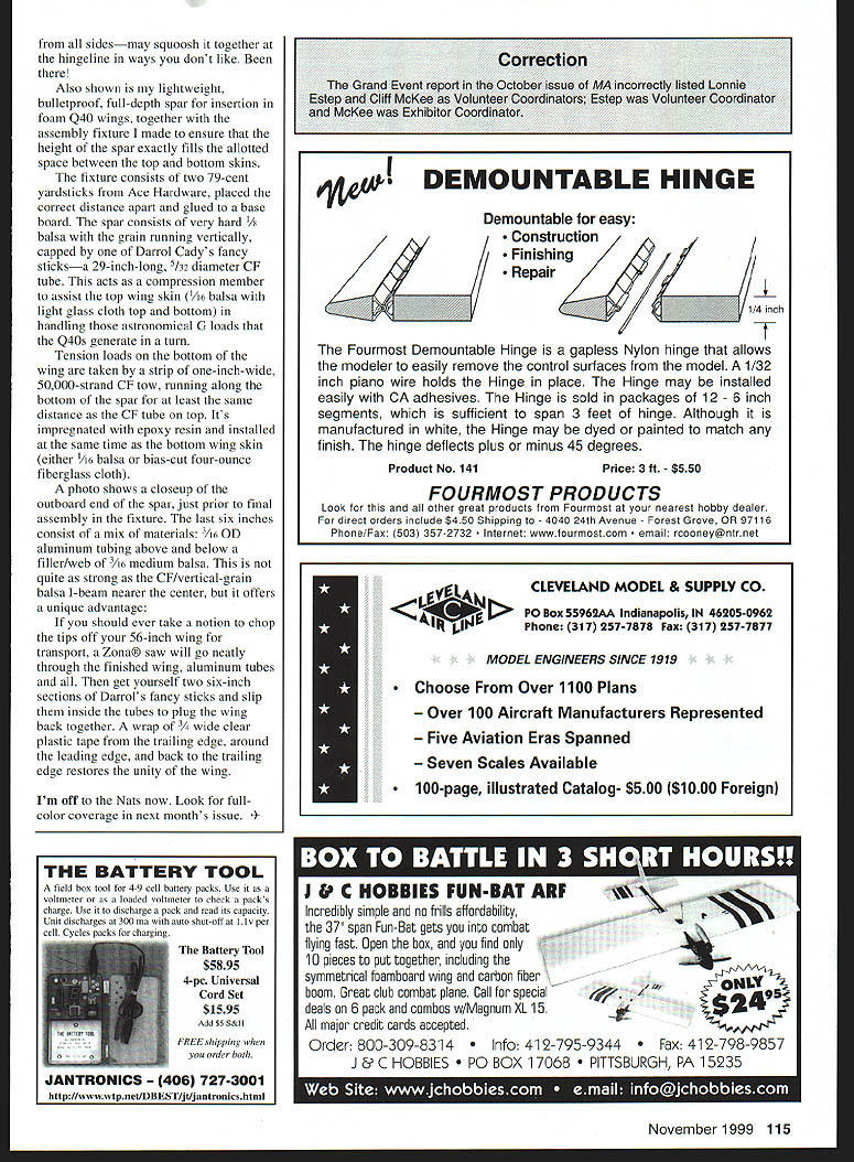
Also shown is my lightweight, bulletproof, full-depth spar for insertion in foam Q40 wings, together with the assembly fixture I made to ensure that the height of the spar exactly fills the allotted space between the top and bottom skins.
The fixture consists of two 79-cent yardsticks from Ace Hardware, placed the correct distance apart and glued to a base board. The spar consists of very hard 1/8-inch balsa with the grain running vertically, capped by one of Darrol Cady's fancy sticks—a 29-inch-long, 3/32-inch-diameter carbon-fiber tube. This acts as a compression member to assist the top wing skin (1/16-inch balsa with light glass cloth top and bottom) in handling those astronomical G loads that the Q40s generate in a turn.
Tension loads on the bottom of the wing are taken by a strip of one-inch-wide, 50,000-strand carbon-fiber tow, running along the bottom of the spar for at least the same distance as the CF tube on top. It's impregnated with epoxy resin and installed at the same time as the bottom wing skin (either 1/16-inch balsa or bias-cut 4-ounce fiberglass cloth).
A photo shows a closeup of the outboard end of the spar, just prior to final assembly in the fixture. The last six inches consist of a mix of materials: 1/16-inch OD aluminum tubing above and below a filler/web of 3/16-inch medium balsa. This is not quite as strong as the CF/vertical-grain balsa I-beam nearer the center, but it offers a unique advantage:
- If you should ever take a notion to chop the tips off your 56-inch wing for transport, a Zona® saw will go neatly through the finished wing, aluminum tubes and all. Then get yourself two six-inch sections of Darrol's fancy sticks and slip them inside the tubes to plug the wing back together. A wrap of 3/4-inch-wide clear plastic tape from the trailing edge, around the leading edge, and back to the trailing edge restores the unity of the wing.
I'm off to the Nats now. Look for full-color coverage in next month's issue. +
Transcribed from original scans by AI. Minor OCR errors may remain.

