
Radio Control: Scale
Bob & Dolly Wischer
LANDING GEAR LOCATION
A reader asked about the effect on ground handling, takeoff and landing when wheel centers are displaced forward or aft of the optimum location.
Experience shows:
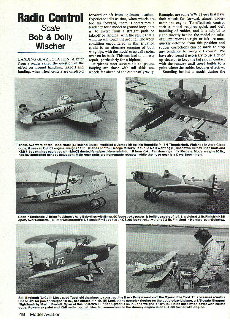
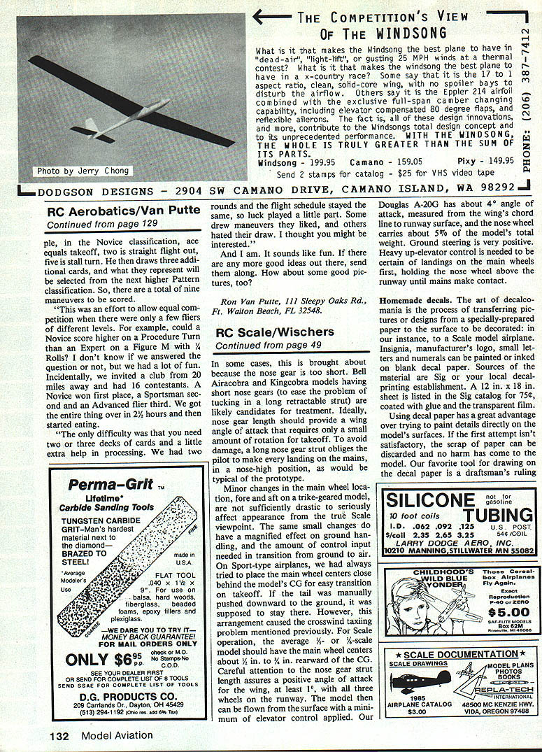
- When wheels are too far forward, models can ground-loop (swing off the straight path on takeoff or landing). A wing tip may touch the ground; worst case, alternate scraping of both tips can flip the model onto its back. Biplanes are particularly vulnerable.
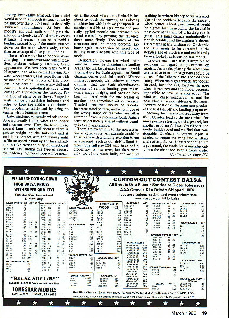
- Aircraft with tail skids and wheels far ahead of the center of gravity (CG), such as some WW I types with wheels almost under the engine, are most susceptible. Controlling such models requires quick, deft rudder work and is aided by standing directly behind the model at takeoff so excursions left/right are seen immediately. A bit of up-elevator to keep the tail skid on the runway until rudder authority builds is often necessary.
- Landing is easier when the approach path passes the pilot closely (rear view), rather than over the pilot’s head. To avoid ground-looping, aim to touch down on the main wheels rather than attempting a three-point landing on these types.
- Propeller wash helps stabilize and gives rudder authority; using an engine with adequate power minimizes the problem.
Later airplanes that have main wheels spaced forward typically use a tailwheel and a longer tail moment arm. This reduces ground-loop tendency because the tailwheel keeps contact until speed is sufficient for the fin and rudder to take over directional control. The greatest risk is when the tailwheel is just touching or carrying little weight; a synchronized bit of up-elevator with partially applied throttle presses the tailwheel down more firmly. Too much of this and the model may lift off again. Again, a rear view during takeoff and landing is helpful.
Deliberately moving wheels rearward or upward, or changing landing-gear shape, is readily noticed and harms scale appearance. Small changes give doubtful benefit. Many otherwise correct models are spoiled by altered landing gear—shape, height or position changed for handling reasons—often creating more harm than good. Treaded tires that should be smooth, incorrect tread patterns, and wrong wheel-hub shapes or diameters are common scale faults; prominent scale features shouldn’t be drastically altered except in rare, well-justified cases.
Exceptions:
- If a full-size prototype had an unusual or nonstandard gear position that causes clear handling problems not documented for modelers, a small, discreet change can be justified. Example: a de Havilland 71 racer model whose gear was so far rearward it tended to nose over on grass. Moving the model’s wheel centers about 1/2 in. forward eliminated the nose-over tendency without noticeably affecting appearance. Such corrections should be caught at the design stage if possible.
Tricycle Gears and Main-Wheel Placement
- For tricycle gear models, copying the full-size wheel centers relative to CG is usually correct. If the main gear wheels are too far forward (near the CG), the nose wheel load is reduced and taxiing in a crosswind becomes difficult—the nose wheel tends to skid sideways. However, forward main-gear placement gives the best takeoff and landing characteristics.
- Moving the mains rearward (away from the CG) increases load on the nose wheel for more positive steering on the ground but creates another problem: on takeoff considerable up-elevator may be needed to rotate the wing into lift. When lift finally occurs the model often leaps into the air at an unrealistically steep climb angle.
- Some models (e.g., Bell Airacobra and Kingcobra replicas) are built with short nose gear to mimic the prototype. Short nose gear can lead to rotation problems; conversely, overly long nose gear forces the pilot to land on the mains in a nose-high attitude. Aim for a nose-gear length and geometry that provide a positive angle of attack for the wing on the ground.
Recommended Placement for Sport/Scale Models
- For 1/8- or 1/6-scale sport and scale models, a good rule is to place main wheel centers about 1 in. to 1-1/2 in. rearward of the CG. This gives an easier transition on takeoff while keeping ground control acceptable.
- Ensure the nose-gear strut length provides at least about 1° positive wing angle of attack with all three wheels on the runway. This lets the model fly off the surface with minimal elevator input.
- Example: the authors’ Douglas A-20G has about 4° angle of attack (wing chord line to runway) and the nose wheel carries roughly 50% of the model’s weight. Ground steering is very positive; heavy up-elevator is required to ensure mains touch first and hold the nose wheel off the runway until the mains make contact.
HOMEMADE DECALS
Decalcomania lets you transfer insignia, logos, letters and numerals to models using specially prepared decal paper (sources: SIG, local decal printers). A 12 in. x 18 in. sheet is commonly available.
Tools and materials:
- Draftsman’s ruling pen (good for lines and circles when used with a draftsman’s bow compass)
- Straightedge or draftsman’s plastic triangle
- India ink for black; thinned enamel for color (avoid over-thinning)
- Fine-tipped artists' brushes for filling
- Rub-on letters/numerals (graphic art industry)
- Clear epoxy or polyurethane varnish for overcoating
- Hobeco Solvaset or Krasel Super Microsol for conforming decals to compound curves
Technique — ruling pen method:
- Draw outlines (use straightedge). Do not attempt freehand unless skilled.
- Fill the inner areas with fine brushes or the ruling pen used as a paint brush.
- For small lettering (<1/2 in.), consider rub-on characters—they’re easier but more expensive.
- Protect artwork from fuel and wear by spraying a clear epoxy over the decal sheet before cutting. Use light coats to avoid buildup; match gloss/flatness with hardener mixture as needed. Polyurethane varnish may be used but gives less control over gloss.
Technique — reverse-cut transfers:
- Spray decal sheet with the required color enamel or dope, then apply clear epoxy (or use color epoxy).
- Turn the dried sheet over and pencil characters on the reverse (backwards).
- Cut out individual characters, soak briefly in water, and slide them off the backing onto the model. Characters will be soft and loose—use care to align; a drop of water helps straighten bends and aligns pieces.
- This method is useful for large printed material (license or AMA numbers) and decorative stripes.
Conforming decals:
- Decal sheet resists compound curves because the lacquer backing is a solid sheet. Use Solvaset or Super Microsol over the decal before the glue hardens to soften and allow conformity to rivet impressions or panel lines.
Rub-on letters:
- Rub-on sheets work well on hard surfaces, not as well on open fabric. Misplaced characters can often be lifted with cellophane tape. Alignment is easier when working on a flat surface (decal paper) rather than directly on the model.
MORE HOBBYNOXY COLORS
Petit Paint Co. (Hobbynoxy) released U.S. insignia colors with Federal Standard (FS) references:
Insignia Red
- FS 11136 (gloss) and FS 31136 (matte)
- Formula: 15 parts H66 Dark Red + 1 part H85 Bright Red
Insignia White
- FS 17875 (gloss) and FS 37875 (matte)
- Formula: 10 parts H10 White + 10 drops H81 Black + 6 drops H49 Cut Yellow + 4 drops H33 Stimson Green
- Two other FS numbers close to white: 37855 and 37886
Insignia Blue
- FS 15044 (gloss) and FS 35044 (matte) — original WWII USAAF/USN shade
- Formula: 3 parts H24 Dark Blue + 2 parts H67 Maroon + 1 part H61 Black
Sea Blue (later Navy gloss)
- FS 15042 (gloss only) — used late WWII and Korean conflict; Navy aircraft used Sea Blue overall, often substituting it in national markings
- Formula: 3 parts H81 Black + 2 parts H33 Stimson Green + 1 part H24 Dark Blue
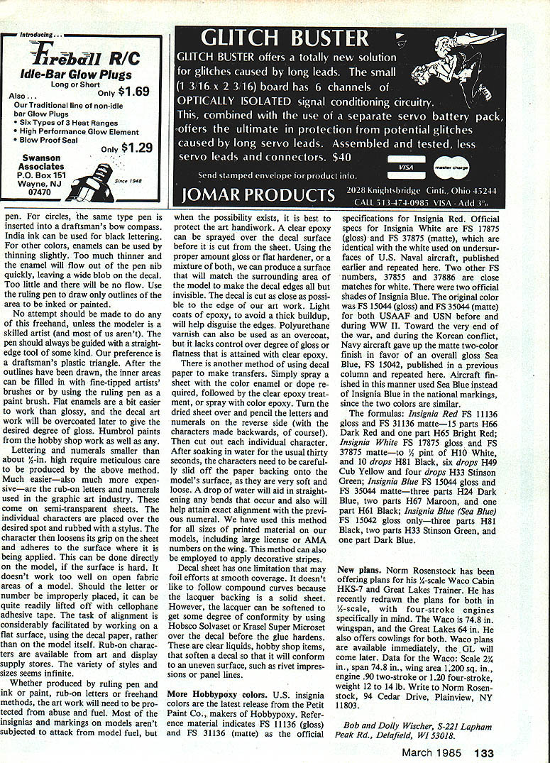
NEW PLANS
Norm Rosenstock has redrawn plans of his Waco Cabin HKS-7 and Great Lakes Trainer in 1/4-scale for four-stroke engines. He also offers cowls for both.
Waco HKS-7 data:
- Scale: 2-1/2 in.
- Wingspan: 74.8 in.
- Wing area: 1,200 sq. in.
- Engine: .90 two-stroke or 1.20 four-stroke
- Weight: 12–14 lb
Great Lakes Trainer:
- Wingspan: 64 in.
- (Plans available later)
Contact: Norm Rosenstock, 94 Cedar Drive, Plainview, NY 11803.
Bob and Dolly Wischer, S-221 Lapham Peak Rd., Delafield, WI 53018.
Transcribed from original scans by AI. Minor OCR errors may remain.

