
Radio Control: Scale
Bob & Dolly Wischer
Report from Paris
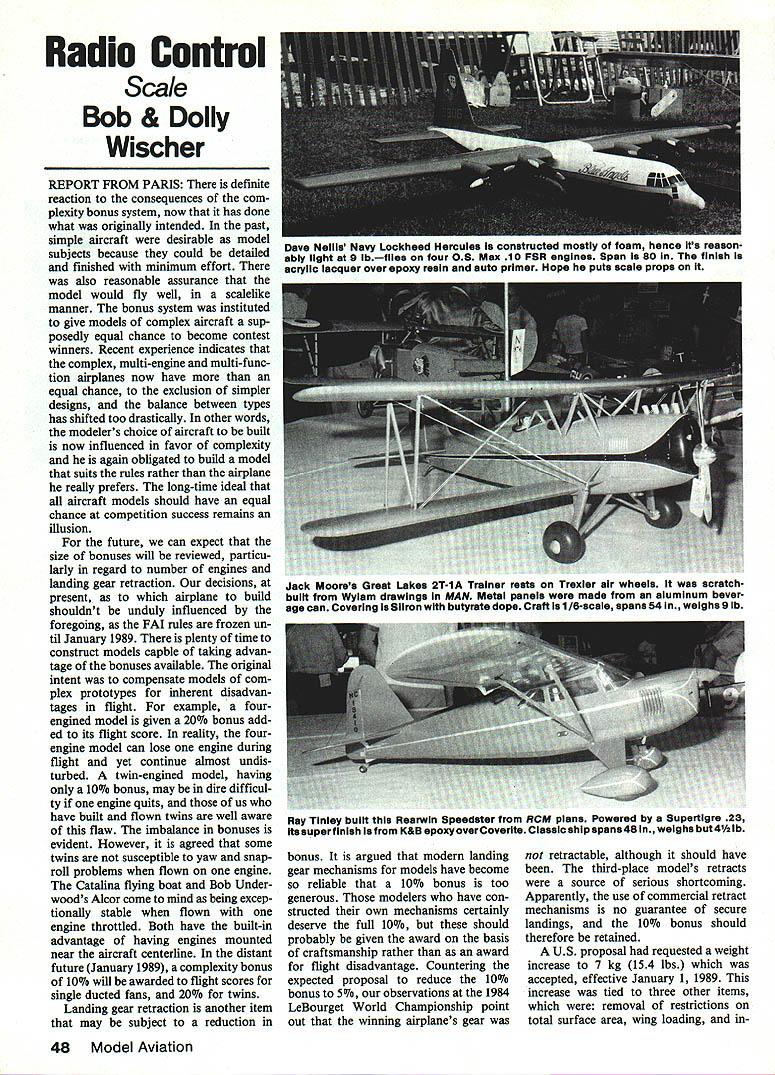
There is definite reaction to the consequences of the complexity-bonus system, now that it has done what was originally intended. In the past, simple aircraft were desirable as model subjects because they could be detailed and finished with minimum effort. There was also reasonable assurance that the model would fly well, in a scalelike manner. The bonus system was instituted to give models of complex aircraft a supposedly equal chance to become contest winners.
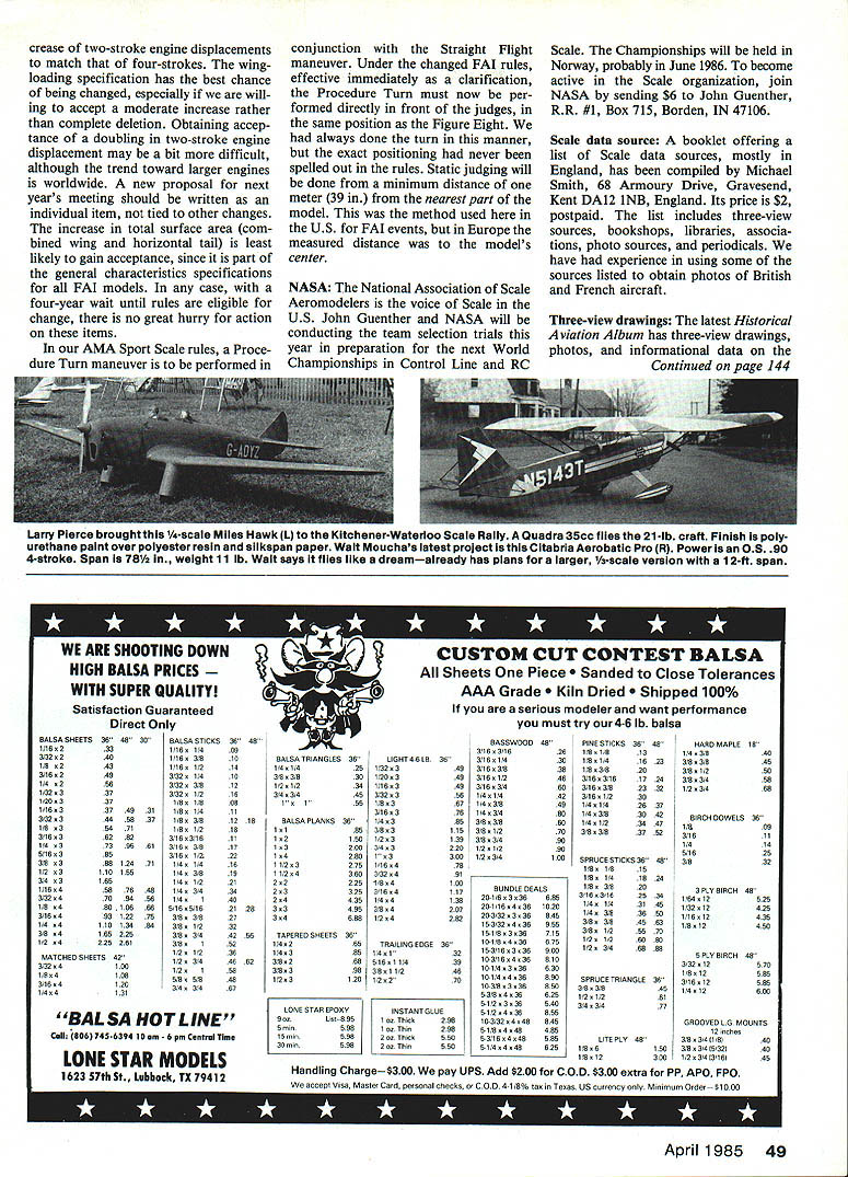
Recent experience indicates that the complex, multi-engine and multi-function airplanes now have more than an equal chance, to the exclusion of simpler designs, and the balance between types has shifted too drastically. In other words, the modeler's choice of aircraft to be built is now influenced in favor of complexity and he is again obligated to build a model that suits the rules rather than the airplane he really prefers. The long-time ideal that all aircraft models should have an equal chance at competition success remains an illusion.
For the future, we can expect that the size of bonuses will be reviewed, particularly in regard to number of engines and landing-gear retraction. Our decisions, at present, as to which airplane to build shouldn't be unduly influenced by the foregoing, as the FAI rules are frozen until January 1989. There is plenty of time to construct models capable of taking advantage of the bonuses available.
The original intent was to compensate models of complex prototypes for inherent disadvantages in flight. For example, a four-engined model is given a 20% bonus added to its flight score. In reality, the four-engined model can lose one engine during flight and yet continue almost undisturbed. A twin-engined model, having only a 10% bonus, may be in dire difficulty if one engine quits, and those of us who have built and flown twins are well aware of this flaw. The imbalance in bonuses is evident. However, it is agreed that some twins are not susceptible to yaw and snap-roll problems when flown on one engine. The Catalina flying boat and Bob Underwood's Alcor come to mind as being exceptionally stable when flown with one engine throttled. Both have the built-in advantage of having engines mounted near the aircraft centerline. In the distant future (January 1989), a complexity bonus of 10% will be awarded to flight scores for single ducted-fans, and 20% for twins.
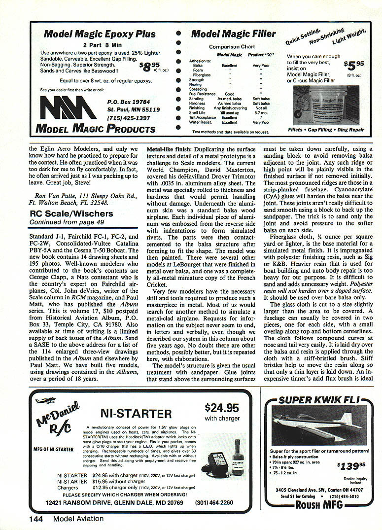
Landing-gear retraction is another item that may be subject to a reduction in bonus. It is argued that modern landing-gear mechanisms for models have become so reliable that a 10% bonus is too generous. Those modelers who have constructed their own mechanisms certainly deserve the full 10%, but these should probably be given the award on the basis of craftsmanship rather than as an award for flight disadvantage. Countering the expected proposal to reduce the 10% bonus to 5%, our observations at the 1984 Le Bourget World Championship point out that the winning airplane's gear was out. The third-place model's retracts were a source of serious shortcoming. Apparently, the use of commercial retract mechanisms is no guarantee of secure landings, and hence the 10% bonus should therefore be retained.
A U.S. proposal had requested a weight increase to 7 kg (15.4 lbs), which was accepted, effective January 1, 1989. This increase was tied to three other items, which were:
- removal of restrictions on total surface area,
- modification of wing-loading limits, and
- increase of two-stroke engine displacements to match that of four-strokes.
The wing-loading specification has the best chance of being changed, especially if we are willing to accept a moderate increase rather than complete deletion. Obtaining acceptance of a doubling in two-stroke engine displacement may be a bit more difficult, although the trend toward larger engines is worldwide. A new proposal for next year's meeting should be written as an individual item, not tied to other changes. The increase in total surface area (combined wing and horizontal tail) is least likely to gain acceptance, since it is part of the general characteristics specifications for all FAI models. In any case, with a four-year wait until rules are eligible for change, there is no great hurry for action on these items.
Procedure Turn and AMA Sport Scale Rules
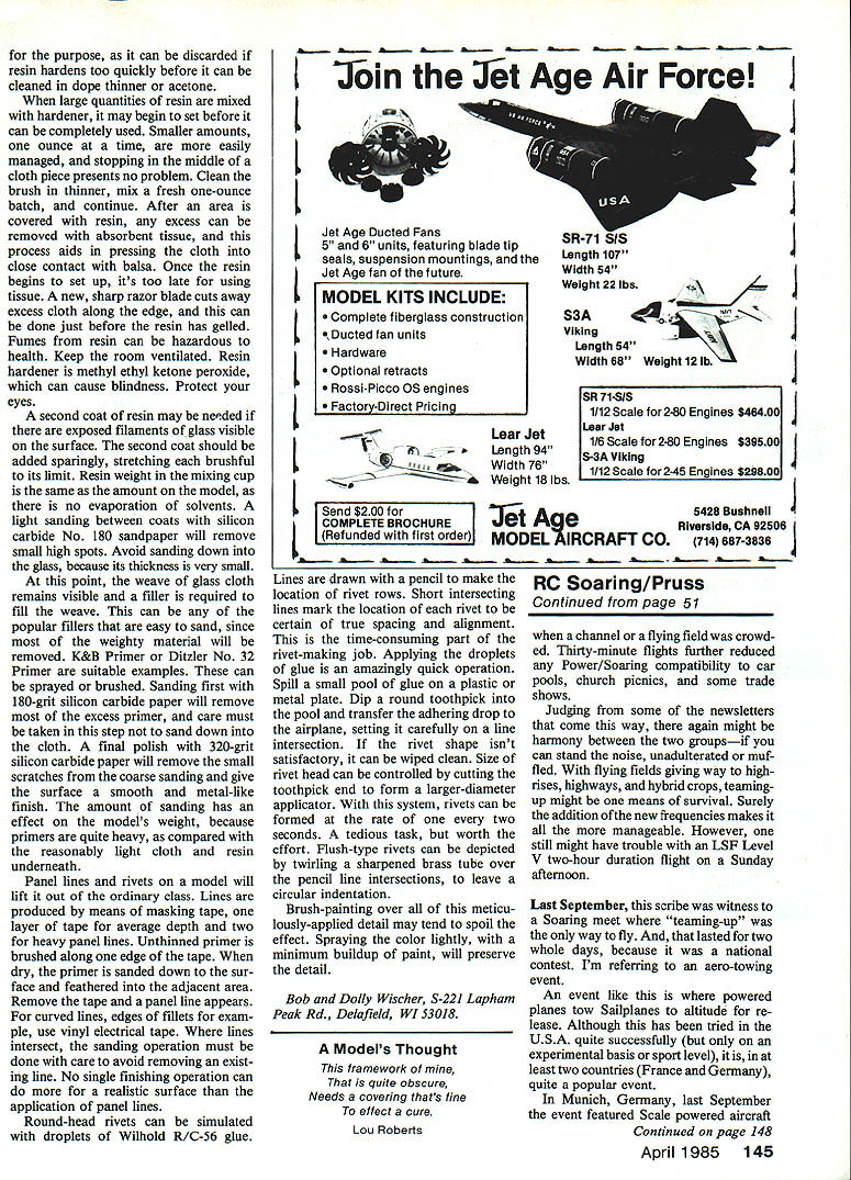
In our AMA Sport Scale rules, a Procedure Turn maneuver is to be performed in conjunction with the Straight Flight maneuver. Under the changed FAI rules, effective immediately as a clarification, the Procedure Turn must now be performed directly in front of the judges, in the same position as the Figure Eight. We had always done the turn in this manner, but the exact positioning had never been spelled out in the rules. Static judging will be done from a minimum distance of one meter (39 in.) from the nearest part of the model. This was the method used here in the U.S. for FAI events, but in Europe the measured distance was to the model's center.
NASA
The National Association of Scale Aeromodelers (NASA) is the voice of Scale in the U.S. John Guenther and NASA will be conducting the team-selection trials this year in preparation for the next World Championships in Control Line and RC Scale. The Championships will be held in Norway, probably in June 1986. To become active in the Scale organization, join NASA by sending $6 to John Guenther, R.R. #1, Box 715, Borden, IN 47106.
Scale Data Source
A booklet offering a list of scale data sources, mostly in England, has been compiled by Michael Smith, 68 Armoy Drive, Gravesend, Kent DA12 1NB, England. Its price is $2, postpaid. The list includes three-view sources, bookshops, libraries, associations, photo sources, and periodicals. We have had experience in using some of the sources listed to obtain photos of British and French aircraft.
Three-View Drawings
The latest Historical Aviation Album has three-view drawings, photos, and informational data on the Standard J-1, Fairchild FC-1, FC-2, and FC-2W, the Consolidated-Vultee Catalina PBY-5A, and the Cessna T-50 Bobcat. The new book contains 14 drawing sheets and 195 photos.
Well-known modelers who contributed to the book's contents are George Clapp, a Nats contestant who is the country's expert on Fairchild airplanes; Col. John deVries, writer of the Scale column in RCM magazine; and Paul Matt, who has published the Album series. This is volume 17, $10 postpaid from Historical Aviation Album, P.O. Box 33, Temple City, CA 91780. Also available at time of writing is a limited supply of back issues of the Album. Send a SASE to the above address for a list of the 114 enlarged three-view drawings published in the Album and elsewhere by Paul Matt. We have built five models using drawings contained in the Albums over a period of 18 years.
Metal-Like Finish
Duplicating the surface texture and detail of a metal prototype is a challenge to Scale modelers. The current World Champion, David Masterton, covered his de Havilland Drover Trimotor with .0035 in. aluminum-alloy sheet. The metal was specially rolled to thickness and hardness that would permit handling without damage. Underneath the aluminum skin was a standard balsa wood airplane. Each individual piece of aluminum was embossed from the reverse side with indentations to form simulated rivets. The parts were then contact-cemented to the balsa structure after being formed to fit the shape. The model was then painted. There were several other models at Le Bourget that were finished in metal over balsa, and one was a completely all-metal miniature copy of the French Cricket.
Very few modelers have the necessary skill and tools required to produce such a masterpiece in metal. Most of us would search for another method to simulate a metal-clad airplane. Requests for information on the subject never seem to end, in letters and verbally, even though we described our system in this column about five years ago. No doubt there are other methods, possibly better, but it is repeated here, with elaborations.
The model's structure is given the usual treatment with sandpaper. Glue joints that stand above the surrounding surfaces must be taken down carefully, using a sanding block to avoid removing balsa adjacent to the joint. Any such ridge or high point will be plainly visible in the finished surface if not removed initially. The most pronounced ridges are those in a strip-planked fuselage. Cyanoacrylate (CyA) glues will harden the balsa near the joint. These joints aren't really difficult to sand smooth using a block to back up the sandpaper. The trick is to sand only the joint and avoid pressure on the softer balsa on each side.
Fiberglass cloth, 1/4 ounce per square yard or lighter, is the base material for a simulated metal finish. It is impregnated with polyester finishing resin, such as Sig or K&B. Heavier resin used for boat building and auto-body repair is too heavy for our purpose; it is difficult to sand and adds unnecessary weight. Polyester resin will harden over a doped surface, but it should be used over bare balsa only.
The glass cloth is cut to a size slightly larger than the area to be covered. A fuselage can usually be covered in two pieces, one for each side, with a small overlap along top and bottom centerlines. The cloth follows compound curves at nose and tail very easily. It is laid dry over the balsa and resin is applied through the cloth with a stiff-bristled brush. Stiff bristles help to move the resin along so that only a thin layer is laid down. An inexpensive tinner's acid flux brush is ideal for this job; it is cheap and can be discarded if the resin hardens before it can be cleaned in dope thinner or acetone. The cloth is smoothed with hands, not with a squeegee, to avoid creating ripples. After the resin has cured it may be rubbed with 320-grit wet-or-dry sandpaper. All cloth threads that stand up should be cut away with sharp scissors, then sanded again. A second coat of resin can be applied and sanded with 320 grit. A final thin coat of resin may be applied and sanded with 400 grit.
Some modelers have used epoxy resins with good results. Epoxy is more expensive and more difficult to sand. It is more waterproof than polyester. If epoxy is used over polyester, the polyester must be fully cured and dry; otherwise the epoxy will not adhere well.
When large quantities of resins are mixed with hardener, they may begin to set before they can be completely used. Smaller amounts, one ounce at a time, are more easily managed, and stopping in the middle of a cloth piece presents no problem. Clean the brush in thinner, mix a fresh one-ounce batch, and continue. After an area is covered with resin, any excess can be removed with absorbent tissue, and this process aids in pressing the cloth into close contact with the balsa. Once the resin begins to set up, it's too late to use tissue. A new, sharp razor blade cuts away excess cloth along the edge, and this can be done just before the resin has gelled.
Fumes from resin can be hazardous to health. Keep the room ventilated. Resin hardener is methyl ethyl ketone peroxide (MEKP), which can cause serious injury; protect your eyes and skin.
A second coat of resin may be needed if there are exposed filaments of glass visible on the surface. The second coat should be added sparingly, stretching each brushful to its limit. Resin weight in the mixing cup is the same as the amount on the model, as there is no evaporation of solvents. A light sanding between coats with silicon-carbide No. 180 sandpaper will remove small high spots. Avoid sanding down into the glass, because its thickness is very small.
At this point, the weave of the glass cloth remains visible and a filler is required to fill the weave. This can be any of the popular fillers that are easy to sand, since most of the weighty material will be removed. K & B Primer or Ditzler No. 32 Primer are suitable examples. The primer can be sprayed or brushed. Sanding first with 180-grit silicon-carbide paper will remove most of the excess primer; care must be taken not to sand down into the cloth. A final polish with 320-grit silicon-carbide paper will remove the small scratches from the coarse sanding and give the surface a smooth and metal-like finish. The amount of sanding has an effect on the model's weight, because primers are quite heavy compared with the reasonably light cloth and resin underneath.
Panel lines and rivets on a model will lift it out of the ordinary class. Lines are produced by means of masking tape: one layer of tape per average depth and two for heavy panel lines. Unthinned primer is brushed along one edge of the tape. When dry, the primer is sanded down to the surface and feathered into the adjacent area. Remove the tape and a panel line appears. For curved lines, such as fillet edges, use vinyl electrical tape. Where lines intersect, the sanding operation must be done with care to avoid removing an existing line. No single finishing operation can do more for a realistic surface than the application of panel lines.
Round-head rivets can be simulated with droplets of Willhold R/C-56 glue. Lines are drawn with a pencil to mark the location of rivet rows. Short intersecting lines mark the location of each rivet to ensure true spacing and alignment. This is the time-consuming part of the rivet-making job. Applying the droplets of glue is an amazingly quick operation. Spill a small pool of glue on a plastic plate. Dip a round toothpick into the pool and transfer the adhering drop to the airplane, setting it carefully on a line intersection. If the rivet shape isn't satisfactory, it can be wiped clean. Size of rivet head can be controlled by the width of the toothpick end to form a larger-diameter applicator. With this system, rivets can be formed at the rate of one every two seconds. A tedious task, but worth the effort.
Flush-type rivets can be depicted by twirling a sharpened brass tube over the pencil line intersections to leave a circular indentation.
Brush-painting over all of this meticulously applied detail may tend to spoil the effect. Spraying the color lightly, with a minimum buildup of paint, will preserve the detail.
Bob and Dolly Wischer S-221 Lapham Peak Rd., Delafield, WI 53018
Transcribed from original scans by AI. Minor OCR errors may remain.

