
Radio Control: Scale
Bob & Dolly Wischer
Four-stroke engines
While visiting England last summer, we were introduced to new (to us) Laser four-stroke engines. Two engines were single-cylinder, valve-in-head types of .61 and .75 cu. in. displacement. Most interesting from the scale modeler's viewpoint was the Laser 1.20 twin, a V-type with two carburetors. These are all bar-stock engines with no castings. The twin has an extremely low idle speed and showed no hesitation on acceleration. Fuel is 20% castor oil; no nitro is needed. Special glow plugs aren't required. British modelers are understandably enthused about their new four-stroke engines.
On the subject of four-strokes, now highly favored for scale models, a common problem is their tendency to backfire from either lean mixtures or flooding. If an engine is loaded with fuel before applying power to the glow plug, a backfire may occur, or the engine may run backward for a few revolutions and then suddenly reverse to the correct direction. When this happens, stop the engine and tighten the prop nut, or remove the prop and examine its back surface.
We have found that the serrations on the front surface of the hub will cut a circular groove in the prop. All is well if the prop shows clear-cut and deep impressions from the drive hub. To restore a damaged prop to usefulness after it has been chewed by the drive hub, lay it on a flat surface and pour epoxy into the groove.
When the propeller on a four-stroke engine isn't properly tightened, the firing and compression impulses on the crankshaft, combined with the inertia of the heavy prop, will tend to set up slight movement at the interface between prop and hub. On full-size airplanes, this can generate enough heat at the interface to char the wood. This, in turn, accelerates the loosening process, with more heat and charring leading to catastrophic failure.
This type of failure is unlikely with our models because the prop mass is much smaller than on full-size aircraft. The worst that can happen is the wearing away of wood, which eventually can lead to the prop spinning free. It has happened to us that the prop came off in flight. The prop was found and repaired with epoxy in the groove, as described. The expensive sleeved nut and washer from the O.S. Gemini are gone forever. We consider ourselves fortunate that it didn't happen on the flight line with people gathered around.
There is a tendency to regard the four-stroke engine as rather benign because it runs quietly at lower speed. A few calculations of actual prop tip velocity are revealing. A .60 two-stroke with an 11-in. prop turning 11,000 rpm has a tip velocity of about 360 mph. A 1.20 four-stroke with a 16-in. prop turning only 9,000 rpm has a tip velocity of about 430 mph. We wouldn't like to be nicked by either one, but the four-stroke could easily remove some necessary body parts. Even a large 18-in. prop at only 6,000 rpm has a very high tip velocity.
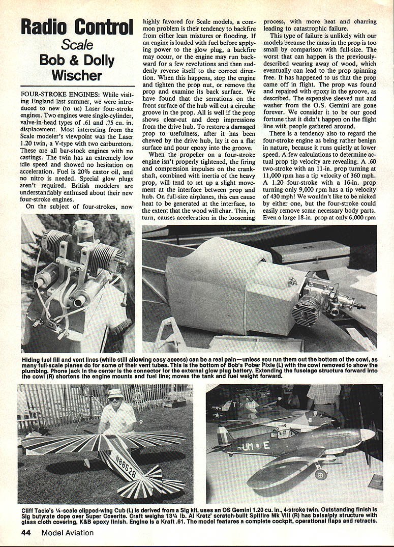
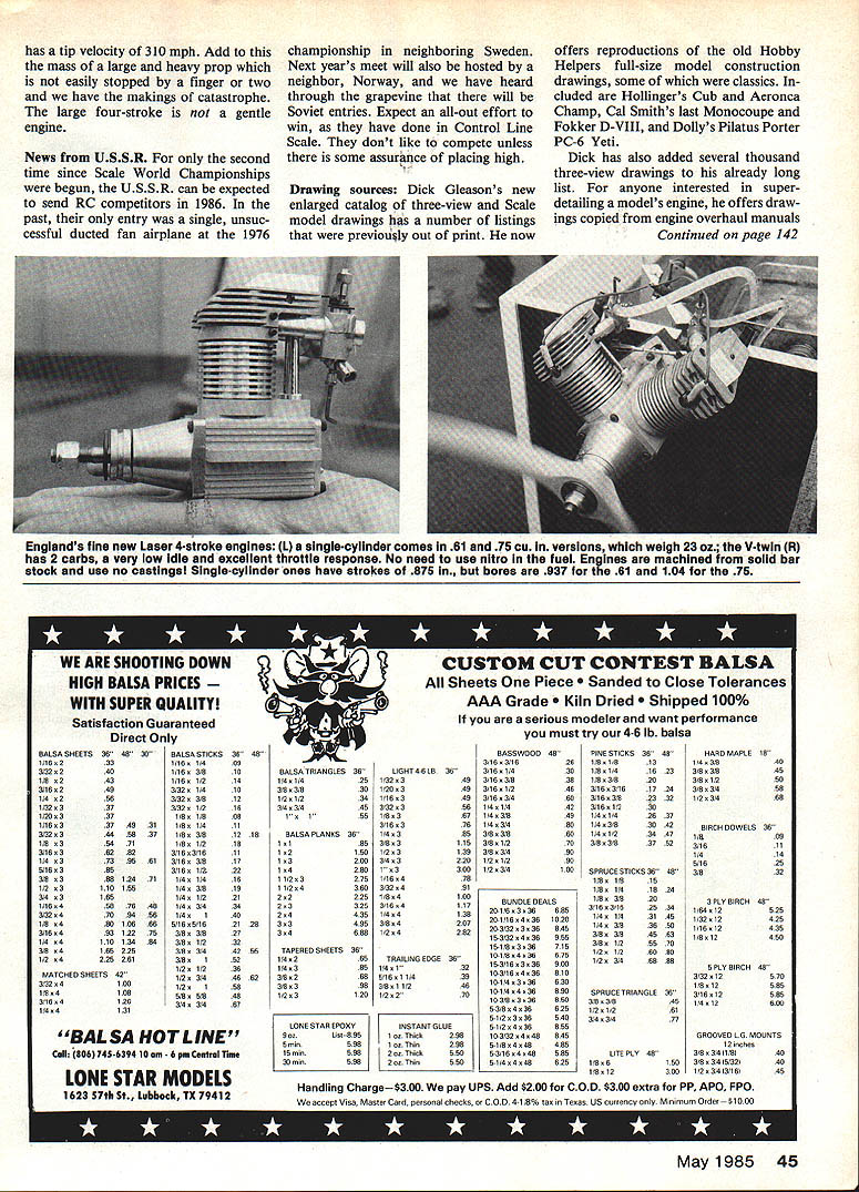
Hiding fuel-fill and vent lines while still allowing easy access can be a real sin—unless they are run out the bottom of the cowl. On full-size planes some vent tubes exit the bottom.
News from U.S.S.R.
For only the second time since Scale World Championships were begun, the U.S.S.R. can be expected to send RC competitors in 1986. In the past, their only entry was a single, unsuccessful ducted-fan airplane at the 1976 championship in neighboring Sweden. Next year's meet will also be hosted by a neighbor, Norway, and we have heard through the grapevine that there will be Soviet entries. Expect an all-out effort to win, as they have done in Control Line. They don't like to compete unless there is some assurance of placing high.
Drawing sources
Dick Gleason's new enlarged catalog of three-view and scale model drawings has a number of listings that were previously out of print. He now offers reproductions of the old Hobby Helpers full-size model construction drawings, some of which were classics. Included are Hollinger's Cub and Aeronca Champ, Cal Smith's last Monocoupe and Fokker D-VIII, and Dolly's Pilatus Porter PC-6 Yeti. Dick has also added several thousand three-view drawings to his already long list.
For anyone interested in super-detailing a model's engine, he offers drawings copied from engine overhaul manuals and descriptive data sheets. He also has reproductions from the drawings of aircraft and engines shown in the 1934 Air Commerce Aircraft Year Book. Sixty-one model drawings by Paul Lindberg (gas and rubber-powered) from Popular Aviation magazine are listed, as are 54 Earl Stahl scale plans from MAN, Air Trails, and Air Age. Catalog price is $1.00 from Gleason Enterprises, 1704—29th Ave. S.E., Rt. 2, Box 125, Austin, Minn. 55912.
Detailed scale multi-view drawings are being produced for documentation and model design of the Curtiss Jenny JN-4, Taylor Brothers Chummy, and North American Mustang P-51B and C. The drawings are available in three scale ratios: 1/8, 1/4, and 1/2. In the 1/4 ratio, drawing size is 24 x 36 in. The Jenny drawing represents a JN-4 flown by Neta Snook, who used the airplane for the flight training of Amelia Earhart. The Taylor Chummy was C.G. Taylor's earliest design that led to development of the Cub, eventually known as the Piper Cub. In its early form the airplane had an open cockpit and a radial engine; photos of the Chummy are also offered. The Mustang drawings are on four sheets, made from factory blueprints and North American documents, "Aerodynamic Dimensional Data on P-51B/C Airplanes." For details and prices, send a SASE to Charles L. Neely, 2703 E. Goshen Ave., Visalia, CA 93291.
Fuel apparatus
Providing fuel to an engine would appear to be a simple matter. On scale models with completely enclosed engine and fuel tank, there may be complexities when it is undesirable to disassemble the airplane for fuel servicing. A portion of the cowling can be made removable, provided there is no objection to non-scale lines, so that a filler tube becomes accessible. If the full-size airplane already has hatch openings in its cowl, these can be used for fuel supply entrances. Most aircraft have no such convenient spots to hide the necessary plastic tubes, and we are therefore obliged to resort to another method.
On airplanes with a completely cowled engine, we run the fuel fill and vent tubes out the bottom at the rear of the cowl. This is the area where cooling air from the engine is normally exhausted on the prototype as well as on the model. A small bit of tube visible in this space isn't really non-scale, because full-size planes often have tubes extending here for battery-box vent and fuel-tank overflow.
The typical model system now has three tubes to the tank:
- One to feed the carburetor.
- Two extending downward for tank filling and venting while fuel is being pumped into the model.
In operation, we connect the electric fuel pump to the lower tube of the pair entering the tank and use the upper tube as an air vent. When fuel begins to run from the vent tube it signals a full tank. To avoid spillage, a length of tube can be connected to the vent line to carry excess fuel back to the supply bottle. As the tank nears capacity, bubbles appear in this tube to signal stopping the pump. The return line to the bottle prevents spilling raw fuel on the grass beneath the model. Fuel kills grass, and the club field has a row of dead spots in the area where models are fueled.
Almost all of us are now using muffler pressure into the tank to promote reliable fuel flow, and this adds complication to the system. A tee is needed in the vent tube and is connected to the muffler. Unless both fill and vent tubes are plugged after filling, muffler pressure is lost while the engine is operating. To prevent this loss, insert a machine screw (4-40 x 1/2) into the tube end after filling.
Because an electric fuel pump will fill the tank faster than fuel can be vented through the overflow tube, there is some risk of considerable flow into the carburetor due to pressure build-up in a full tank. On an upright engine, flooding can result. On a side-mounted or inverted engine, fuel may be dumped inside the cowl from the carburetor. This can be avoided by stopping the pump when the first bubbles appear in the vent tube. The fuel tube to the carburetor is then full, and the engine is automatically primed, ready for starting. Fill and vent tubes must be identified in some way so that fuel is never pumped into the muffler through the tee connection.
A tank made from sheet brass or tin-plated steel can be shaped to fit any fuselage. Three brass tubes are soldered into its forward surface for fuel line, fill and vent. One advantage of a custom-made tank is that the fill tube can be bent downward so that its end rests on the tank bottom. It can then be used for both filling and emptying. Of course, this tube must be plugged immediately after filling, or fuel will siphon until the tank is empty. The principal reason for making a tank is to get a shape that will fit under the cowl without being visible inside the cockpit.
Four of our last six scale models have tanks made from .005-in. brass, assembled by soldering. All have shapes to fit the fuselage for maximum capacity and have V-bottoms so that all fuel can be evacuated after flying. Brass corrodes in fuel, and it is suspected that fuel remaining in a brass tank could eventually cause leaks. The tank in our Emeraude is now 14 years old and has a clunk-weighted silicone internal tube for pickup. The tube has never been changed, which is a worry at times, but the sound of the weight bouncing off the brass walls is reassuring. The final soldering operation in assembling the tank seals the pickup tube inside permanently. We now find it hard to believe that a silicone pickup tube inside a fuel tank needs to be replaced periodically if the tank is emptied after each flying session.
During the design stages of a new model, one of the first considerations should be fuel-tank location. The tank installation must not be an afterthought. In many cases it has been necessary to build the fuselage structure with an extension inside the model's engine cowl in order to get the tank as far forward as possible. This is done for weight distribution, to avoid adding nose weight, and to keep the fuel line short. It is rarely practicable to place the tank in the optimum position with its center 1/2 in. below the needle valve. Mounting the engine at an angle to one side permits some variation in needle-valve location, but the angle is also determined to some extent by the muffler. Muffler pressure helps to smooth out the minor difficulties that arise from a tank being mounted too low.
Viewing the bottom of our cowl, what we see is a pair of silicone tubes held in place with aluminum clamps and wood screws. Between the tubes is an aluminum bracket with a miniature phone jack (Radio Shack 274-253) for connection of the starting battery to the glow plug. Use a heavy wire for this connection—No. 18 is preferred. The wire from the starting battery will have a miniature phone plug (Radio Shack 274-286). This brings all service to a central point, almost invisible and yet easily accessible. Scale appearance is preserved.
Bob and Dolly Wischer S221 Lapham Peak Rd., Delafield, WI 53018.
Transcribed from original scans by AI. Minor OCR errors may remain.

