
Radio Control: Scale
Bob & Dolly Wischer S-221 Lapham Peak Rd., Delafield, WI 53018
Fiberglass over foam
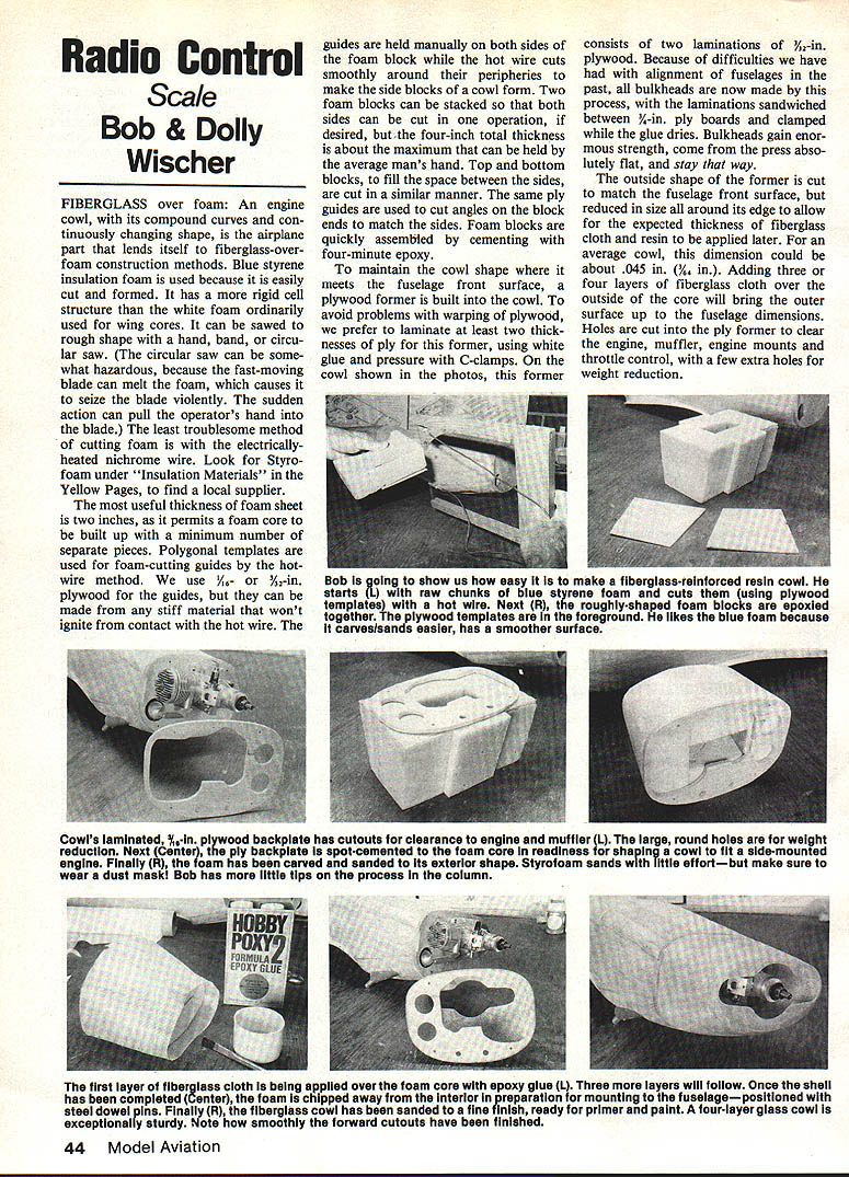
An engine cowl, with its compound curves and continuously changing shape, is an airplane part that lends itself to fiberglass-over-foam construction methods. Blue styrene insulation foam is used because it is easily cut and formed and has a more rigid cell structure than the white foam ordinarily used for wing cores.
- Cutting methods:
- Hand, band, or circular saw: can be used to saw the foam to rough shape. A circular saw can be hazardous because the fast-moving blade may melt the foam and seize the blade, possibly pulling the operator's hand.
- Electrically heated nichrome (hot) wire: least troublesome method; look for Styrofoam under "Insulation Materials" in the Yellow Pages to find a supplier.
A useful foam sheet thickness is two inches, allowing a core to be built up with a minimum number of pieces. Polygonal templates are used as hot-wire cutting guides. We use 1/16- or 1/8-in. plywood for the guides, but any stiff material that won't ignite on contact with the hot wire will do. Guides are held manually on both sides of the foam block while the hot wire cuts smoothly around their peripheries.
Two foam blocks can be stacked so both sides are cut in one operation; about four inches total thickness is the practical maximum an average person can hold. Top and bottom blocks, to fill the space between the sides, are cut similarly. The same plywood guides are used to cut angles on the block ends to match the sides. Foam blocks are quickly assembled by cementing with four-minute epoxy.
Former and backplate
To maintain the cowl shape where it meets the fuselage front surface, a plywood former (backplate) is built into the cowl. To avoid warping, laminate at least two thicknesses of ply, glued with white glue and clamped under pressure with C-clamps. The authors used two laminations of 3/32-in. plywood sandwiched between 1/8-in. ply boards while the glue dried. This process yields bulkheads of great strength that remain flat.
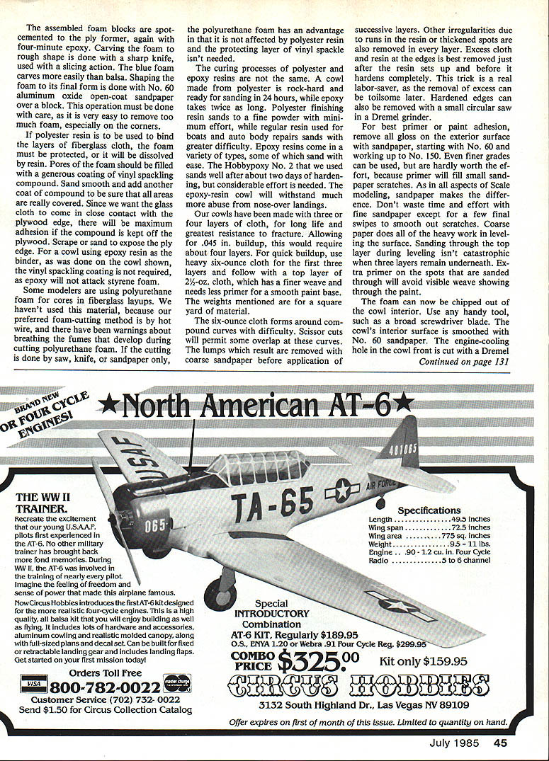
Cut the outside shape of the former to match the fuselage front surface, but reduce its size around the edge to allow for the expected fiberglass cloth and resin thickness (about .045 in. is a typical allowance). Adding three or four layers of fiberglass cloth over the outside of the core brings the outer surface up to fuselage dimensions. Cut holes in the former to clear the engine, muffler, engine mounts, and throttle control; add a few extra holes for weight reduction.
The assembled foam blocks are spot-cemented to the plywood former with four-minute epoxy.
Shaping and protecting the foam
Carve the foam to rough shape with a sharp knife using a slicing action; blue foam carves easily. Final shaping is done with No. 60 aluminum-oxide open-coat sandpaper over a block. Be careful—it's easy to remove too much material, especially at corners.
If polyester resin is to be used, protect the foam because polyester will dissolve styrene foam. Fill foam pores with a generous coating of vinyl spackling compound, sand smooth, and add another coat to ensure full coverage. Keep the compound off the plywood edge so the glass cloth can come in close contact with the ply for maximum adhesion—scrape or sand to expose the ply edge.
Some modelers use polyurethane foam for cores; it is not affected by polyester resin so the vinyl spackle layer isn't needed. However, polyurethane is not recommended for hot-wire cutting because fumes can be hazardous.
Resins, cloth, and layering
Polyester and epoxy resins cure differently:
- Polyester resin: rock-hard and ready for sanding in about 24 hours; finishing resin sands to a fine powder with relatively little effort.
- Epoxy resin: generally takes longer to harden (about twice as long for some types); some epoxy formulations sand more easily than others. Hobbypoxy No. 2 sands reasonably well after about two days of hardening. Epoxy-resin cowls better withstand abuse from nose-over landings.
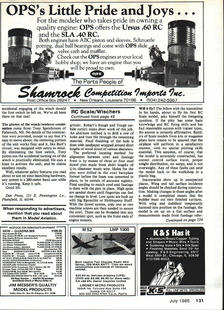
For durability and fracture resistance, use three or four layers of cloth. Allowing for a .045-in. buildup, about four layers are typical. For quicker buildup, use heavy six-ounce cloth for the first layers and finish with a top layer of 2-1/2-oz. cloth for a finer weave and less primer needed for a smooth paint base (weights are per square yard).
The six-ounce cloth can be difficult to form around compound curves; scissor cuts permit overlaps. Remove lumps with coarse sandpaper before applying successive layers. Remove irregularities (runs, thick spots) at each layer. Excess cloth and resin at the edges is easiest to remove just after the resin sets up but before it fully hardens. Hardened edges can be removed later with a small circular saw or a Dremel grinder.
Sanding and painting
Remove all gloss from the exterior surface before primer or paint:
- Start with No. 60 sandpaper for heavy leveling.
- Progress to No. 150; finer grades are usually unnecessary because primer fills small scratches.
Don't waste time with very fine paper except for final smoothing. Sanding through the top layer during leveling isn't catastrophic if multiple layers remain underneath; add extra primer over spots that are sanded through to avoid weave showing through the paint.
Final interior work and cutouts
Chip out the foam from the cowl interior with a broad screwdriver or similar tool. Smooth the interior with No. 60 sandpaper. Cut the engine-cowl hole in the front with a Dremel tool and a grinder; Robart's Rough and Tough carbide cutters work well. Alternate methods include drilling a row of holes and filing through the remaining material. Finish round openings with sandpaper wrapped around short wood dowels of various diameters.
Locating and mounting
The preferred alignment method between cowl and fuselage front is three or four steel dowel pins made from short lengths of 1/8-in.-diameter music wire. Drill holes for the pins in the cowl backplate before cementing the foam to ensure accurate registry. With the pins in place, do final sanding to match cowl and fuselage: sand high spots until fingertips feel no change in level; build up low spots with Sig Epoxolite or Hobbypoxy Stuff. With the dowel system, only one or two machine screws are needed to secure the cowl; these can be threaded into convenient spots such as the front ends of engine mounts.
RC Scale: Preflight checks and setup
Will it fly?
If the pilot has basic RC flying skills and success with trainer types, a scale model will generally perform satisfactorily—provided the model is accurately constructed, has correct control surface travel, proper weight distribution, no warps, and is not overweight. Any of those faults can force the model back to the workshop.
Incidence and alignment checks
Check wing and tail surface incidence angles during construction—changes after completion require cutting into finished surfaces. Temporarily fasten wing and stabilizer to the fuselage, set the model on a flat surface, and take measurements from fuselage reference points to the centerline, leading, and trailing edges to confirm agreement with drawings. A Robart incidence meter is helpful.
Check horizontal alignment of wing and stabilizer by sighting from the rear (view from 5–8 feet along the fuselage centerline) and compare the distance from each stabilizer tip to the wing's surface. Ensure the fin is truly vertical and parallel with the fuselage.
Detecting wing warps and washout
A warped wing causes undesirable turning tendencies and may cause one half of the wing to stall unexpectedly. To detect warps:
- Place the wing inverted on a table with the trailing edge at eye level.
- Close one eye and sight along the wing centerline from about five feet, comparing the trailing-edge line with the wing's lower surface. An equal amount of lower surface should be visible on both sides when the eye shifts from one wing half to the other.
- Increase accuracy by raising the trailing edge or lowering the eye until a minimum amount of lower surface is visible.
- As you shift gaze from centerline toward the tip, the trailing edge should appear lower near the tip if washout is present; both sides should match.
You can also hold the wing at arm's length, inverted, and sight along the centerline from the trailing edge. A Robart incidence meter can detect warps as well.
Balance (center of gravity)
For first flights, set the balance point at about 25% of the wing chord aft of the leading edge. Mark spots on the wing bottom near the fuselage with masking tape so you can slide fingertips rearward to the marked spot and lift to check balance. If the tail drops, add nose weight. After initial flights you may remove some weight to shift the CG rearward for increased elevator sensitivity.
- Nose-heavy effects:
- Refuses to spin.
- Does not increase speed; adding nose weight increases total weight, requiring extra takeoff speed.
- Requires up-elevator trim, increasing wing angle of attack and drag.
- Up-trim increases the angular difference between wing and stabilizer incidences (longitudinal dihedral), which stabilizes pitch.
- Tail-heavy (too little nose weight):
- Requires down-elevator trim for level flight, reducing longitudinal dihedral.
- Becomes unstable in pitch, with the nose hunting up and down.
Example: The authors' Ryan SCW improved greatly when 12 ounces of lead were added to the nose—converting it from difficult to fly into a much more manageable airplane.
Control surface travel
For first flights, use less control travel rather than more.
- Ailerons: Small movements are normally sufficient; too much travel can induce tip stalls at low speed.
- Elevator: Too little elevator travel is not particularly risky if the balance point is correct; you only need enough up-elevator to get the model down for a landing. Elevator travel can be increased later for aerobatics.
Corrections and news
Correction: An April 1985 column stated that the winning airplane at the Le Bourget World Championships had non-retractable landing gear "although it should have been." David Bilutis pointed out that the prototype DH Drover had fixed gear. Notes from an interview with David Masterton confirm the Drover gear was non-retractable. Bonus points for retractable landing gear are not necessary for winning a championship.
News update: Group Captain James Pelly-Fry sent word about the steam-powered radio-controlled model built by David Parker (described in the January 1985 column). The model flew in the hands of its builder at a public demonstration at the Westlands Aircraft Day; it later caught fire while airborne and fell.
Transcribed from original scans by AI. Minor OCR errors may remain.

