
Radio Control: Scale
By Bob and Dolly Wischer
Measurements
A reader in Finland asks for elaboration on methods of taking measurements of full-scale airplanes. In past columns we have praised the virtues of having the prototype available for examination, photos, and dimensional data, but neglected to explain procedures. We made the incorrect assumption that everyone knew the necessary steps. Juhani Sederholm asks specifically for the method of determining exactly the shape of an unknown airfoil, without damaging the surface of an airplane, after permission is granted to make dimensional checks. When the airfoil designation is known, its outlines can be copied from a standard reference source such as the Handbook for Airfoil Sections by M. S. Rice.
Most important is to approach the airplane prepared with a few items of equipment in addition to the usual 100-foot steel tape measure.
- Giant wooden sliding caliper (see fabrication details below)
- Flexible steel tape measure
- Cord for determining camber line
- Small radius gauge for leading edge work
- Long strips of paper (adding-machine tape)
- Self-stick tape
- Step ladders
- Sketch pad and pencil
- Camera with 135mm+ lens for distortion-reduced photos
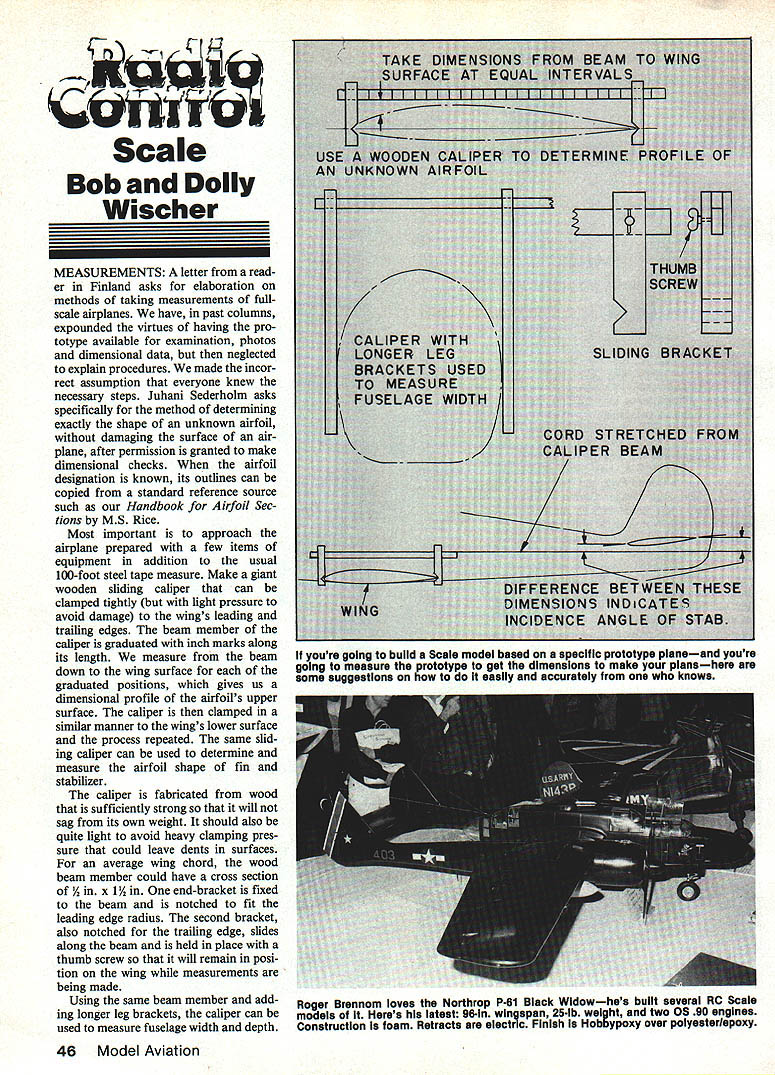
Make a giant wooden sliding caliper that can be clamped tightly (but with light pressure to avoid damage) to the wing's leading and trailing edges. The beam member of the caliper is graduated with inch marks along its length. Measure from the beam down to the wing surface for each of the graduated positions to obtain a dimensional profile of the airfoil's upper surface. Then clamp the caliper to the wing's lower surface and repeat the process. The same sliding caliper can be used to determine and measure the airfoil shape of the fin and stabilizer.
The caliper should be fabricated from wood strong enough to resist sagging yet light enough to avoid heavy clamping pressure that could dent surfaces. For an average wing chord, the beam member might have a cross section of 1/2 in. x 1 1/2 in. One end bracket is fixed to the beam and notched to fit the leading edge radius. The second bracket, also notched for the trailing edge, slides along the beam and is held in position with a thumb screw so it will remain on the wing while measurements are being made.
Using the same beam member and adding longer leg brackets, the caliper can measure fuselage width and depth. This is especially handy when the fuselage cross section is an odd oval. The caliper can also obtain dimensions of odd shapes such as the aft end of an engine cowl that is neither round nor oval. Long strips of paper can be wrapped around the fuselage or cowl and held in place with bits of self-stick tape.
From a known, fixed point on each side of the fuselage (a panel line, for example), use a felt-tip pen to mark the tape in regular increments above and below the point. Now the caliper can be adjusted to measure fuselage width at intermediate points to ascertain the odd-shaped cross-section coordinates. This requires the help of an assistant or two to guide the caliper ends equally on both sides of the fuselage. The graduations need not be used for measurement—after the caliper has been lifted from the fuselage, merely measure across the gap at the bracket tips to read the dimension directly. Carry short step ladders to reach upper portions of the fuselage.
With the caliper clamped to the wing near its root, lay a cord along the beam's upper surface and stretch it rearward to the trailing edge. The marks on the cord give the wing's camber line. A flexible steel tape measure is handy for taking the cord measurements back to a reference line. For small modeling jobs, a two-foot folding metal carpenter's ruler may be substituted. For accurate leading-edge measurements, a small radius gauge makes it easy to copy the shape.
When wing fillets, fillet fairings, and the root are of strange shapes, measure them by taping paper strips to the surface and measuring from a reference line. The strips can be fit together to form cross sections. Another method is to use a contour plotter; however, such a device is usually more expensive than most modelers want to spend.
Good lift.
Dan Pruss 131 E. Pennington Ln., Plainfield, IL 60544
Move the cord forward to the stabilizer to determine the angular difference between wing and stabilizer incidence angles. The cord also indicates the wing incidence relative to the fuselage centerline. If the stabilizer is adjustable, make measurements from the center of its adjustable range.
Measuring along curved surfaces can be tricky. A tape measure stretched along the fuselage side from the rear of the propeller to the tail post follows a curve, and the resulting measurement will be too long. Avoid the false reading by measuring first from the propeller to a point on the fuselage defined by a vertical line such as the engine cowl or a door edge. Then measure from this vertical line to the elevator hinge line while stretching the tape parallel to the fuselage center. Add the dimension from elevator hinge to tail post to obtain the true fuselage length as it would be drawn in the side view. The long dimension along the curved fuselage surface can still be used during model design as a cross-check for top-view length; the difference in a 1/4-scale model can be an inch or two for an airplane with a wide fuselage.
Building a model from the prototype without a reliable three-view drawing can be time-consuming. Several days may be spent taking dimensions and making photos, and second or third trips to the airport or museum are normal. Photos are good reminders of shapes, but usually of minimal value for dimensions because of distortion. If the airplane is outdoors and the camera can be at a great distance, a long telephoto lens can produce relatively distortion-free photos useful for working drawings. For a standard 35mm SLR camera, the lens should be 135mm or greater, and exposures should be made with the lens aimed squarely at right angles to the fuselage side or front. A top view is nearly impossible with a camera. There really is no substitute for a tape measure and time spent gathering data.
Taking dimensions from a full-size aircraft is always done from datum lines or points. Fuselage length dimensions are commonly taken from the propeller's rear surface or from a prominent vertical line chosen for convenience. Feature locations are then measured fore and aft from this line. Critical dimensions include distances to the wing leading edge (or spar) and to the landing gear wheel centers. Tapered wings can be troublesome, particularly when there are no parallel lines of leading edge, trailing edge, or even a straight-through main wing spar delineated by rivet rows. A cord stretched between tips will establish an arbitrary line from which to measure.
A stretched cord along the top longeron or along a prominent panel line helps locate the relationship between fuselage centerline and the propeller shaft. Shaft location and thrust offsets are difficult to locate accurately, and these elements can have a profound effect on flight as well as scale appearance. Extend the stretched cord forward to the plane of the propeller's rotation and measure the distance to the floor. Measure the distance from the prop shaft centerline to the floor. The difference between the two dimensions can then be placed accurately on the model's construction drawings.
Most measurements of a full-scale aircraft are straightforward: use a steel tape and always start from fixed reference points or lines. Once the basics are begun, the job can proceed quickly. A sketch pad and pencil, using freehand technique, will provide a record to be later transposed into accurate drawings. Freehand sketches can be crude and rudimentary; there is no need to reproduce the true shape of every part in the freehand stage—only the dimensions and relationships to other parts are needed. Drawings can be developed later in the design stage from these dimensions and photographs.
Look for straight lines in the aircraft structure. Except for nose cowlings and tip outlines, it is often surprising how few curves are found in airplanes. We have seen three-view drawings showing curving fuselage outlines when, in reality, the outline should have been a succession of straight lines joined end to end. This is a key feature of sheet-metal fuselages of older airplanes: the aluminum is formed in one direction only, and there are few compound curves, since those require costly tooling or hand-working of the metal. The Spitfire, with its many curves, is an exception. Many modern aircraft also have extensive tooling for complex shapes. On older types, look for straight lines; when curves exist, they often represent wooden stringers on a wood-former superstructure.
New publication
A specialty journal of interest to scale modelers is being launched. 1919–1939 Air Wars will carry information detailing aircraft, performance, armament, combat handling, and pilot reports for the years between 1919 and 1939. It will feature restorers, replica-builders, scale modelers, historians, and museums. Issue No. 1 includes articles on the 1936 Legion Condor in Spain, Waco military aircraft, Fiat CR.32, and Heinkel He-51A-1 drawings. It is a quarterly publication. Write to: Air Wars, 8931 Kittyhawk Ave., Los Angeles, CA 90045.
Composites
Greatest strength for weight, other than with exotic materials such as Kevlar or carbon fiber, can be derived from proper use of commonly used materials: balsa, plywood, and fiberglass. In the past 10 years almost all of the plywood in our models has been laminated from two or more layers of plywood or ply plus balsa.
The chief advantage, besides strength, is the absence of warping that seems a continual fault of single-sheet plywood. We use white glue in a very thin film between layers and compress the sheet between flat boards with C-clamps. Minimum drying (setting) time in warm conditions is an hour, after which pressure can be released and the part cut to shape. To be absolutely certain of no later warping, increase the curing time to eight hours.
Examples of recent applications include a wing-box frame for a canopy-support made from three layers of 3/32-in. ply. The part was cut from the sheet with a very narrow rim, about 3/16-in. square in section and 9-in. wide; it has tremendous strength. If the model noses over in tall grass, there is negligible risk of fracture, as it will easily support the plane's weight. Fuselage bulkheads made by laminating two layers of 1/8-in. or 3/32-in. ply can be thinned out to a very narrow frame equal in weight to ordinary balsa formers—but with enormous strength by comparison. Laminating three layers—two of plywood with a balsa core—affords light weight with added rigidity, and the resulting part has greater thickness for cementing surface.
For fuselage bulkheads, soft 1/4-in. balsa with 1/32-in. ply faces is an ideal combination and can be used for weight reduction in large models. The process may seem wasteful because the bulkhead center is cut out, but the scraps can be used for smaller parts at the fuselage aft end. Leftovers are always used.
External composites—fiberglass cloth laminated over balsa—are probably the most common combination. Their weakness is in compression strength. Air loads on a wing or stabilizer will likely never cause damage, but the shock of a hard landing can cause compression fractures on the bottom surfaces. Sudden, rapidly applied loads from snap maneuvers or high-speed changes of direction could lead to failure. Once continuity of the glass fibers is lost, there is no quick and easy repair.
Using epoxy resin in place of polyester will increase strength by 15%–20%, and thicker balsa sheeting (3/8 in. instead of 1/4 in.) will provide an additional safety factor. Even though this weakness exists with fiberglass cloth, it remains our best method of building-in strength by composite construction because of the large area covered on flight surfaces.
The point is that fiberglass does not make a wing or stabilizer invulnerable. After a hard landing, look for compression fractures where strength is impaired by cutouts for retractable landing gear, and on a stabilizer's lower surface where it attaches to the fuselage. These same points are vulnerable on airplanes not covered with fiberglass. Airplanes that come apart in midair, and we have seen and heard of a number of these, probably had a history of bad-landing damage before the catastrophe.
Bob and Dolly Wischer S-221 Lapham Peak Rd., Delafield, WI 53018
Transcribed from original scans by AI. Minor OCR errors may remain.

